- Catalogs
- Teledyne Relays
- 122C
- Company
- Products
- Catalogs
- News & Trends
- Exhibitions
122C
1 /6Pages

122C
1 /6Pages
Catalog excerpts

B^TELEDYNE RELAYS A Unit of Teledyne Electronics and Communications CENTIGRID® MAGNETIC-LATCHING COMMERCIAL RELAYS DPDT CMOS COMPATIBLE DESCRIPTION The 122C Centigrid® magnetic-latching relay is an ultraminiature, hermetically sealed, armature relay capable of being directly driven by most IC logic families. Its low profile height and .100” grid spaced terminals, which precludes the need for spreader pads, make it ideal for applications where extreme packaging density and/or close PC board spacing are required. The basic operating function and internal structure are similar to Teledyne's TO-5, 422 relay series. The 122C is capable of meeting Teledyne Relays' T2R® requirements. The following unique construction features and manufacturing techniques provide overall high reliability and excellent resistance to environmental extremes: The Series 122C relay has internal silicon diodes for coil suppression, Zener diodes to protect the MOSFET gate inputs, and N-channel enhancement-mode MOSFET chips, which enable direct relay interfacing with most microprocessor and IC logic families (CMOS, TTL and MOS). The 122C magnetic-latching relay is ideally suited for applications where coil operating power must be minimized. The relays can be operated with a short-duration pulse. After the contacts have transferred, no external coil power is required. The magnetic-latching feature of the Series 122C relay provides a “memory” capability, since the relays will not reset upon removal of coil power. SERIES DESIGNATION By virtue of its inherently low intercontact capacitance and contact circuit losses, the 122C relay has proven to be an excellent ultraminiature RF switch for frequency ranges well into the UHF spectrum. A typical RF application for this Centigrid® relay is in handheld radio transceivers, wherein the combined features of good RF performance, small size, low coil power dissipation and high reliability make it a preferred method of transmit-receive switching (see Figure 1). ENVIRONMENTAL AND PHYSICAL SPECIFICATIONS All welded construction. Unique uni-frame design providing high magnetic efficiency and mechanical rigidity. High force/mass ratios to withstand shock and vibration. Advanced cleaning techniques provide maximum assurance of internal cleanliness. Precious metal alloy contact material with gold plating assures excellent high current and dry circuit switching capabilities. PRINCIPLE OF OPERATION Energizing Coil B produces a magnetic field opposing the holding flux of the permanent magnet in Circuit B. As this net holding force decreases, the attractive force in the air gap of Circuit A, which also results from the flux of the permanent magnet, becomes great enough to break the armature free of Core B, and snap it into a closed position against Core A. The armature then remains in this position upon removal of energy from Coil B, but will snap back to position B upon energizing Coil A. Since operation depends upon cancellation of a magnetic field, it is necessary to apply the correct polarity to the relay coils as indicated on the relay schematic. When latching relays are installed in equipment, the latch and reset coils should not be pulsed simultaneously. Coils should not be pulsed with less than rated coil voltage and the pulse width should be a minimum of three times the specified operate time of the relay. If these conditions are not followed, it is possible for the relay to be in the magnetically neutral position. ©2003 TELEDYNE RELAYS SPECIFICATIONS ARE SUBJECT TO CHANGE WITHOUT NOTICE
Open the catalog to page 1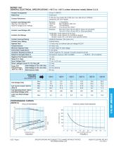
SERIES 122C GENERAL ELECTRICAL SPECIFICATIONS (-65°C to +125°C unless otherwise noted) (Notes 2 & 3) CENTIGRID® AND TO-5 Contact Arrangement SPECIFICATIONS ARE SUBJECT TO CHANGE WITHOUT NOTICE www.teledynerelays.com
Open the catalog to page 2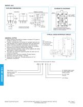
SERIES 122C OUTLINE DIMENSIONS SCHEMATIC DIAGRAMS PIN 10: +SUPPLY PIN 5: –SUPPLY PINS 4 & 9: GATE DIMENSIONS ARE SHOWN IN INCHES (MILLIMETERS) SCHEMATIC IS VIEWED FROM TERMINALS. CONTACTS SHOWN IN POSITION RESULTING WHEN COIL A LAST ENERGIZED. TYPICAL CMOS INTERFACE CIRCUIT Vr GENERAL NOTES 1. Relay contacts will exhibit no chatter in excess of 10 µsec or transfer in excess of 1 µsec. 2. “Typical” characteristics are based on available data and are best estimates. No on-going verification tests are performed. 3. Unless otherwise specified, parameters are initial values. 4. Pins 4, 5 and 9 must...
Open the catalog to page 3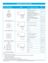
Appendix A: Spacer Pads Pad designation and bottom view dimensions Notes: 1. Spacer pad material: Polyester film. 2. To specify an “M4” or “M9” spacer pad, refer to the mounting variants portion of the part numbering example in the applicable datasheet. 3. Dimensions are in inches (mm). 4. Unless otherwise specified, tolerance is ± .010 (.25). 5. Add 10 mΩ to the contact resistance show in the datasheet. 6. Add 0.01 oz. (0.25 g) to the weight of the relay assembly shown in the datasheet. © 2008 Teledyne Relays
Open the catalog to page 4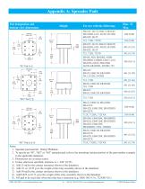
Pad designation and bottom view dimensions Height For use with the following: 1. Spreader pad material: Diallyl Phthalate. 2. To specify an “M”, “M2” or “M3” spreader pad, refer to the mounting variants portion of the part number example in the applicable datasheet. 4. Unless otherwise specified, tolerance is ± .010” (0.25). 5/. Add 25 mQ to the contact resistance shown in the datasheet. 6/. Add .01 oz. (0.25 g) to the weight of the relay assembly shown in the datasheet. 7/. Add 50 mQ to the contact resistance shown in the datasheet. 8/. Add 0.025 oz (0.71 g) to the weight of the relay assembly...
Open the catalog to page 5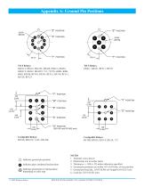
Appendix A: Ground Pin Positions Indicates ground pin position Indicates glass insulated lead position Indicates ground pin or lead position depending on relay type NOTES 1. Terminal views shown 2. Dimensions are in inches (mm) 3. Tolerances: ± .010 (±.25) unless otherwise specified 4. Ground pin positions are within .015 (0.38) dia. of true position 5. Ground pin head dia., 0.035 (0.89) ref: height 0.010 (0.25) ref. 6. Lead dia. 0.017 (0.43) nom. SPECIFICATIONS SUBJECT TO CHANGE
Open the catalog to page 6All Teledyne Relays catalogs and technical brochures
 Space product selction guide
62 Pages
 Product overview
28 Pages
 732
7326 Pages
 722
7223 Pages
 712
7126 Pages
 H-33S
H-33S6 Pages
 Series HR412/ HRS412
10 Pages
 E3P Series
4 Pages
 LS10 Series
2 Pages
 Series EMCRT
4 Pages
 S3P series
2 Pages
 Series SQ
2 Pages
 Miniature Matrix
1 Page
 Matrix Selection Guide
28 Pages


Archived catalogs
 Series HR255/HR257
11 Pages
 Series H-32N
6 Pages
 172
1726 Pages


- Single-pole switch
- Switching relay
- Technology switch
- Multipole switch
- Electromechanical switch
- Electromechanical relay
- DC electromechanical relay
- Solid state relay
- Transfer switch
- Power relay
- Printed circuit board electromechanical relay
- DC solid state relay
- AC electromechanical relay
- 12VDC electromechanical relay
- Mechanical switch
- Bistable electromechanical relay
- Interlock electric switch
- Compact electromechanical relay
- Power solid state relay
- 3-pole electric switch