- Catalogs
- Teledyne LeCroy Europe
- WaveExpert Sampling Oscilloscopes
WaveExpert Sampling Oscilloscopes
1 /16Pages

WaveExpert Sampling Oscilloscopes
1 /16Pages
Catalog excerpts
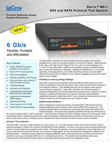
Wide Bandwidth Oscilloscopes for Next Generation Serial Data Standards
Open the catalog to page 1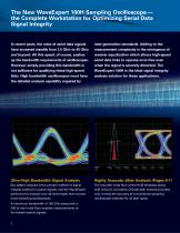
The New WaveExpert 100H Sampling Oscilloscope — the Complete Workstation for Optimizing Serial Data Signal Integrity In recent years, the rates of serial data signals have increased steadily from 2.5 Gb/s to 40 Gb/s and beyond. All this speed, of course, pushes up the bandwidth requirements of oscilloscopes. However, simply providing this bandwidth is not sufficient for qualifying these high-speed links. High bandwidth oscilloscopes must have the detailed analysis capability required by next-generation standards. Adding to the measurement complexity is the emergence of receiver equalization which...
Open the catalog to page 2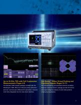
Up to 20 GHz TDR with Full S-parameter Measurements (Pages 4-5) Eye Doctor™ Offers Virtual Probing and Equalized Signals (Pages 10-11) The standard TDR analysis package included with the The Virtual Probing and equalized receiver emulation WaveExpert 100H offers full reference plane calibration features in the Eye Doctor package provide full end-to- and one- and two-port differential S-parameter measure- end signal integrity analysis of serial data systems ment fully integrated into the instrument interface. employing equalization.
Open the catalog to page 3
Integrated TDR Analysis and S-parameter Measurement TDR Analysis with S-parameter Measurement • Single-ended and differential measurements is an essential tool for analyzing the response of backplanes, cables, pc • Fast step (20 ps rise time) boards and other devices. TDR analysis • Sub-millimeter measurement resolution with reference plane calibration and one- • Advanced OSL (Open Short Load) calibration removes effects of cables, fixtures, etc. and two-port differential S-parameter • TRUE differential TDR/TDT • Automated deskew ments are integrated into the user • Accurate S-parameter measurements...
Open the catalog to page 4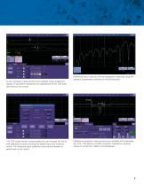
Cursor reactance measurements are available which enable the display of equivalent inductance and capacitance of the TDR trace Differential return loss of a 24-inch backplane measured using the standard S-parameter software on the WaveExpert. The TDR measurement wizard guides the user through the set-up and calibration process ensuring the highest accuracy measure- ments. Full reference plane calibration and channel deskew is Calibrated impedance measurements are available with selectable rise time. This feature provides compliant impedance measure- ments of connectors, cables, and backplanes....
Open the catalog to page 5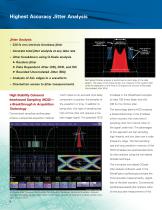
Highest Accuracy Jitter Analysis Jitter Analysis • 230 fs rms intrinsic timebase jitter • Accurate total jitter analysis at any data rate • Jitter breakdown using Q-Scale analysis ® Random jitter ® Data Dependent Jitter (DDj, DCD, and ISI) ® Bounded Uncorrelated Jitter (BUj) • Analysis of ALL edges in a waveform • One-button access to jitter measurements Normalized Q-Scale analysis is performed on each edge of the data pattern. The slope of the linear portion is a measure of the random jitter while the separation of the lines at Q=0 gives the amount of Bounded Uncorrelated Jitter (BUj). High...
Open the catalog to page 6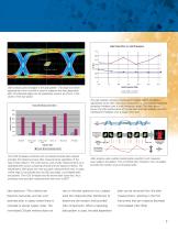
Jitter analysis uses all edges in the data pattern. The slope and mean displacement from nominal is used to measure the data dependent jitter. All individual edges can be separately viewed, as shown in the Total Jitter Measurement Error Baseline KJBusliSi KJltipsffl!) BUUSps BU. 3) us 1(1=429(13 Injected Jitter □ O-ycule ■ ypef.ti in ri-tms*fd r rielli<jU The HCIS timebase combined with normalized Q-Scale jitter analysis provides the highest accuracy jitter measurements regardless of the type of jitter present. This chart shows a set of jitter measurements on a calibrated jitter source comparing...
Open the catalog to page 7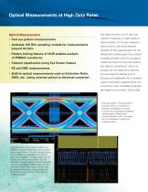
Optical Measurements at High Data Rates Optical Measurements • Fast eye pattern measurements • Available 100 GHz sampling module for measurements • Pattern locking feature of HCIS enables analysis • Channel equalization using Eye Doctor feature • Built-in optical measurements such as Extinction Ratio, OMA, etc. (using external optical to electrical converter) Eye patterns remain one of the most important measures of signal quality in optical systems. In the past, designers were forced to use small statistics samples for this measurement, but the WaveExpert oscilloscope's fast coherent timebase...
Open the catalog to page 8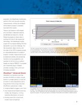
acquisition, the WaveExpert oscilloscope performs the most accurate eye jitter measurements, without the timebase drift problems present in standard equivalent-time scopes. Telecom and datacom technologies are at 40 Gb/s in deployed systems, and 80 Gb/s and beyond in the lab. Measuring signals at these rates is pushing the limits of test equipment technology. The WaveExpert oscilloscope with its industry-leading 100 GHz bandwidth is up to the challenge. The fast acquisition, deep memory, and low jitter of the HCIS timebase provide an unprecedented level of waveform The high measurement throughput...
Open the catalog to page 9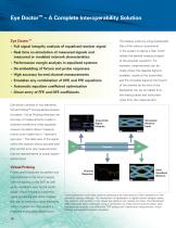
Eye Doctor™ – A Complete Interoperability Solution This feature works by using S-parameter • Full signal integrity analysis of equalized receiver signal files of the various components • Real time co-simulation of measured signals and measured or modeled network characteristics in the system to derive a filter which relates the desired measured signal to the acquired waveform. For • Performance margin analysis in equalized systems • De-embedding of fixture and probe responses made where the cleanest signal is • High accuracy far-end channel measurements available, usually at the transmitter,...
Open the catalog to page 10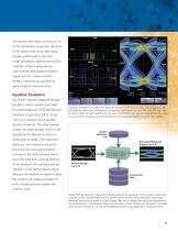
The derived filter takes into account all of the interactions among the elements of the system and transmitter signal including differential to common mode conversion, nearend and far-end crosstalk. Virtual Probing can be used to de-embed probe and fixture responses from measurements thereby improving the accuracy of signal integrity measurements. Equalizer Emulation Eye Doctor features equalized receiver emulation which includes both Feed Forward Equalization (FFE) and Decision Feedback Equalization (DFE), along Equalizer emulation simulates the signal as viewed within the receiver. The component...
Open the catalog to page 11All Teledyne LeCroy Europe catalogs and technical brochures
 T3DSO4000L-HD
19 Pages
 WaveRunner 8000HD
20 Pages
 HDO6000B
20 Pages
 T3DSOH1000 /T3DSOH1000-ISO
15 Pages
 T3DAQ1-16
16 Pages
 T3MIL50 Milli Ohm Meter
6 Pages
 T3PM1006 Digital Power Meter
8 Pages
 Current Probes
4 Pages
 WavePro HD
20 Pages
 WaveRunner 9000
20 Pages
 PeRT3 Phoenix System
16 Pages
 DDR Test Suite
12 Pages
 LabMaster 10 Zi-A
28 Pages
 WaveRunner 8000
24 Pages
 wavesurfer 510
20 Pages
 MDA800 Motor Drive Analyzers
8 Pages
 MIPI M-PHY Protocol Analyzer
4 Pages
 Transmission Line Probes
2 Pages
 WaveSurfer 10 Oscilloscope
12 Pages
 Summit T24 Analyzer
2 Pages
 SierraNet M168
4 Pages
 LabMaster 10 Zi Oscilloscopes
36 Pages
 LabMaster 9 Zi-A Oscilloscopes
36 Pages
 WaveMaster 8 Zi-A Oscilloscopes
36 Pages
 SDA 8 Zi-A Serial Data Analyzers
36 Pages
 DDA 8 Zi-A Disk Drive Analyzers
36 Pages
 WavePro 7 Zi-A Oscilloscopes
28 Pages
 SDA 7 Zi-A Serial Data Analyzers
28 Pages
 DDA 7 Zi-A Disk Drive Analyzers
28 Pages
 HRO 12-bit Oscilloscopes
8 Pages
 HDO8000 High Definition
20 Pages
 HDO6000 / HDO6000-MS High
20 Pages
 WaveRunner 6 Zi Oscilloscopes
28 Pages


Archived catalogs
 HDO4000 / HDO4000-MS High
16 Pages
 Summit T3-16 Analyzer
2 Pages
 Voyager M3i
8 Pages
 WaveSurfer 3000 Oscilloscopes
12 Pages
 WaveJet 300A Oscilloscopes
8 Pages
 Differential Amplifiers
2 Pages
 Current Probes
7 Pages
 HFP SERIES ACTIVE PROBES
4 Pages
 LeCroy Kibra 480 Analyzer
4 Pages
 Vehicle Bus Analyzers
2 Pages
 Signal Integrity Studio
4 Pages
 ArbStudio
8 Pages
 PeRT3 Eagle System
8 Pages
 SPARQ
SPARQ12 Pages
 LogicStudio
8 Pages


- Power supply unit
- DC power supply
- Concentration analyzer
- Automatic analyser
- Benchtop analyser
- Single-output power supply
- Portable analyzer
- Generator
- Digital analyzer
- Multimeter
- Digital multimeter
- Power quality analyzer
- Programmable power supply
- Power meter
- DC/DC power supply
- Data acquisition unit
- High-performance analyzer
- Trace analyzer
- Electrical network analyzer
- 1000 V multimeter