- Catalogs
- Teledyne LeCroy Europe
- Transmission Line Probes
Transmission Line Probes
1 /2Pages

Transmission Line Probes
1 /2Pages
Catalog excerpts
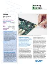
Probing Solutions PP066 High Bandwidth Passive Probe Technical Specifications Electrical Characteristics: Bandwidth Maximum Voltage: Cable Length: Transmission Line Probing The PP066 is a high-bandwidth passive probe designed for the use with the WaveMaster™ and other high-bandwidth oscilloscopes that have 50 Ω input termination.This very low capacitance probe provides an excellent solution for higher frequency applications, especially the probing of transmission lines with 20–100 Ω impedance. Flexibility Interchangeable attenuator tips provide the user a choice of input resistances and sensitivities.The probe cable connection is a standard SMA. PP066 probes are suited to a wide range of design applications including probing of analog and digital IC's commonly found in computer, communications, data storage, and other high-speed designs. Signal Integrity at High Bandwidth When measuring very high frequencies, use of a probe with low input capacitance is the key to preserving signal integrity. A 1 pf active probe, though nominally high impedance, loads a 1 GHz signal with 159 ohm capacitive reactance (X = 1/2π fC). The PP066 preserves high bandwidth content of signals, retaining proper signal shape even for very fast edges. The PP066 passive probe has lower circuit loading at high frequencies than an active probe. PROBING HIGH SPEED SIGNALS Accurately measuring digital waveforms with oscilloscopes becomes increasingly challenging as edge speeds become faster. Often, interconnecting the test circuit to the oscilloscope is the most difficult part of the problem. Designers frequently select an active probe as the tool of choice for this task. However, in many situations a lesser known type of passive probe can provide better performance at a lower cost. Probing any circuit for the purpose of making a measurement will change its operation. This is often the case when it comes to measuring waveforms with high frequency content. Extremely small parasitic elements added to the probe circuit can greatly distort the signal being measured. Probe loading is usually the most significant factor that contributes to waveform distortion. Any real life voltage signal can be diagrammed as a Thévenin equivalent model represented as an ideal voltage source with a series impedance between it and the test point where the probe is connected (see the figure on back). The impedance in the probe to ground forms a voltage divider, which attenuates the measured signal. If the impedances were purely resistive, this effect could be easily compensated for by applying a scalar multiplier to the measured waveform amplitude. However, the reactive portions of the circuit’s source impedance and the measurement probe create a frequency dependent attenuation that cannot be effectively corrected. As the frequency content of the signal being measured increases, even the most minute parasitic capacitance and inductance will impart significant attenuation, greatly distorting the appearance of the measured waveform. Consider an example where we probe a fast digital signal with a 1 ns transition time using a high-quality passive probe. The input impedance of these probes is generally 1 MΩ in parallel with about 10 pF. If the source impedance of the circuit being tested is 30 Ω , the 1 MΩ resistive component of the probe creates virtually no DC attenuation. However, the effect of the capacitance is significant. Using the basic rule to translate rise time into
Open the catalog to page 1
Sales and Service Throughout the World Corporate Headquarters 700 Chestnut Ridge Road Chestnut Ridge, NY 10977 USA http://www.lecroy.com LeCroy Sales Offices: Simplified model of probe loading effects frequency, 1 ns rise time corresponds to approximately 350 MHz. The capacitive reactance of 10 pF at 350 MHz is 45 Ω. So during the 1 ns transition, the impedance in the lower leg of the voltage divider would be 45 Ω rather than 1 MΩ, attenuating the signal by approximately 40%. Since we usually cannot tolerate measurements that include 40% or greater errors, an active probe is often used to measure...
Open the catalog to page 2All Teledyne LeCroy Europe catalogs and technical brochures
 T3DSO4000L-HD
19 Pages
 WaveRunner 8000HD
20 Pages
 HDO6000B
20 Pages
 T3DSOH1000 /T3DSOH1000-ISO
15 Pages
 T3DAQ1-16
16 Pages
 T3MIL50 Milli Ohm Meter
6 Pages
 T3PM1006 Digital Power Meter
8 Pages
 Current Probes
4 Pages
 WavePro HD
20 Pages
 WaveRunner 9000
20 Pages
 PeRT3 Phoenix System
16 Pages
 DDR Test Suite
12 Pages
 LabMaster 10 Zi-A
28 Pages
 WaveRunner 8000
24 Pages
 wavesurfer 510
20 Pages
 MDA800 Motor Drive Analyzers
8 Pages
 MIPI M-PHY Protocol Analyzer
4 Pages
 WaveSurfer 10 Oscilloscope
12 Pages
 Summit T24 Analyzer
2 Pages
 SierraNet M168
4 Pages
 LabMaster 10 Zi Oscilloscopes
36 Pages
 LabMaster 9 Zi-A Oscilloscopes
36 Pages
 WaveMaster 8 Zi-A Oscilloscopes
36 Pages
 SDA 8 Zi-A Serial Data Analyzers
36 Pages
 DDA 8 Zi-A Disk Drive Analyzers
36 Pages
 WavePro 7 Zi-A Oscilloscopes
28 Pages
 SDA 7 Zi-A Serial Data Analyzers
28 Pages
 DDA 7 Zi-A Disk Drive Analyzers
28 Pages
 HRO 12-bit Oscilloscopes
8 Pages
 HDO8000 High Definition
20 Pages
 HDO6000 / HDO6000-MS High
20 Pages
 WaveRunner 6 Zi Oscilloscopes
28 Pages


Archived catalogs
 HDO4000 / HDO4000-MS High
16 Pages
 Summit T3-16 Analyzer
2 Pages
 Voyager M3i
8 Pages
 WaveSurfer 3000 Oscilloscopes
12 Pages
 WaveJet 300A Oscilloscopes
8 Pages
 Differential Amplifiers
2 Pages
 Current Probes
7 Pages
 HFP SERIES ACTIVE PROBES
4 Pages
 LeCroy Kibra 480 Analyzer
4 Pages
 Vehicle Bus Analyzers
2 Pages
 Signal Integrity Studio
4 Pages
 ArbStudio
8 Pages
 PeRT3 Eagle System
8 Pages
 SPARQ
SPARQ12 Pages
 LogicStudio
8 Pages


- Power supply unit
- DC power supply
- Concentration analyzer
- Automatic analyser
- Single-output power supply
- Benchtop analyser
- Portable analyzer
- Generator
- Digital analyzer
- Multimeter
- Digital multimeter
- Power quality analyzer
- Programmable power supply
- Power meter
- DC/DC power supply
- Data acquisition unit
- High-performance analyzer
- Trace analyzer
- Electrical network analyzer
- 1000 V multimeter