- Catalogs
- Teledyne LeCroy Europe
- T3DAQ1-16
T3DAQ1-16
1 /16Pages

T3DAQ1-16
1 /16Pages
Catalog excerpts

T3DAQ1-16 Data Sheet Data Acquisition System Broad Measurement Range DC: up to 1000 Volts AC: up to 750 Volts Current: up to 10A Tools for Improved Debugging 16 Multi-purpose Data Acquisition Channels built on a 6½ digit digital multimeter platform. ore flexible measurements without losing M accuracy. Wide range of measurements – DC/AC voltage and Current, Resistance, Capacitance, Frequency, Period. ore application coverage from a single system. M True-RMS measurements – All ACVoltage and Current ranges give True-RMS readings. xcellent accuracy regardless of the waveform E shape. Built-in cold terminal thermocouple compensation. ccurate Temperature measurements. A USB Device, USB Host and LAN support. emote control of your measurements. R 3 Years Warranty as standard. eliable product gives peace of mind. R Front Panel Connector 12 Multi-Purpose and 4 Current Channels DC/AC Voltage Range DC/AC Current Range
Open the catalog to page 1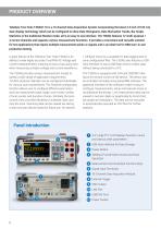
PRODUCT OVERVIEW Teledyne Test Tools T3DAQ1-16 is a 16 channel Data Acquisition System incorporating the latest 4.3 inch (10.92 cm) dual-display technology which can be configured to show Data Histograms, Data fluctuation Trends, Bar Graph, Statistics or the traditional Number mode, all in an easy to use interface. The T3DAQ features 12 multi-purpose + 4 current channels and supports various measurement functions. It provides a convenient and versatile solution for test applications that require multiple measurement points or signals and is an ideal tool for R&D burn-in and production testing....
Open the catalog to page 2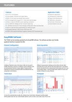
FEATURES Features Application Fields Research Laboratory Dual display, Chinese and English Menu Development Laboratory Calibration Laboratory Automatic Production Test True-RMS AC Voltage and AC Current measuring EasyDMM Software The T3DAQ can be remotely operated by the EasyDMM software. The software provides user friendly graphical interface to operate the DAQ. Channel Configuration Data Acquisition Congure Channels menu in the Scan mode can be used to enable channels as well as to congure various settings such as measurement function, range, speed of measurement. Channels can also be monitored...
Open the catalog to page 3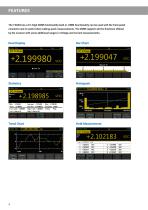
FEATURES The T3DAQ has a 6½ Digit DMM functionality built in. DMM functionality can be used with the front panel connector and is useful when making quick measurements. The DMM supports all the functions offered by the scanner with some additional ranges in Voltage and Current measurements. Dual Display Trend Chart Hold Measurement
Open the catalog to page 4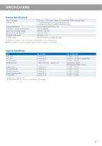
SPECIFICATIONS Scanner Specifications1) Max AC Voltage Contact Life Contact Resistance Channel to channel switching time Maximum switching voltage Maximum switching power Insulation Resistance Connect Type 1) 125 rms or 175 V peak, 100kHz, 0.3 A switched, 125VA ( resistive load ) > 10,0000 operations, at 1 A 30 VDC (at 0.5 Hz) > 100,000 operation, at 0.3 A 125 VDC (at 0.5 Hz) 75 mΩ (maximum at 6 VDC, 1A) 280 ms (typical) 250 VAC, 220 VDC 62.5 VA / 30 W Minimum 1 GΩ Clamp terminal, # 24 AWG wire size Valid when the instrument is used in Scan Mode. For full specifications refer to the tabels below....
Open the catalog to page 5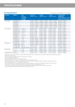
SPECIFICATIONS DC Characteristics Function Accuracy ± (% of reading + % of range) 1) Test Current Or Burden Voltage Temperature coefficient 0 °C to (TCAL °C - 5 °C) (TCAL °C +5 °C) to 50 °C Specifications are for 90-minute warm-up and 100NPLC integration time. For integration time <100NPLC, add the appropriate “RMS Noise Adder” listed in the following table. 10 % over range on all ranges except DCV 1000 V and DCI 10 A range. 3) Relative to calibration standards. 4) For each additional volt over ± 500 V, add 0.03 mV error. 5) For continuous current > 7 A DC or 7 A AC RMS, 30 seconds ON and 30...
Open the catalog to page 6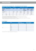
SPECIFICATIONS Performance Versus Integration Time – 50 Hz (60 Hz) Power-line Frequency 1) Integration Time RMS Noise Adder 5) (% of Range) DCV 2 V 200 V Resistance 2 KΩ 20 KΩ 0.0008 0.0005 0.0003 0.0001 0 0 Only 1 NPLC and 10 NPLC ranges are available as Fast and Slow modes respectively when the instrument is used in Scan mode. Typical value. Resolution is defined as the typical 20 V range RMS noise. Normal mode rejection ratio for power-line frequency ± 0.1%. For power-line frequency ± 1%, subtract 20 dB. For ± 3 %, subtract 30 dB. 4) Maximum rate for DCV, DCI, 2-wire resistance and 4-wire...
Open the catalog to page 7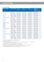
SPECIFICATIONS AC Characteristics Function Range 2) Accuracy ± (% of reading + % of range) 1) Frequency Range Specifications are for 90-minute warm-up, > 3 Hz ac filter and sine wave input. 10 % over range on all ranges except ACV 750 V and ACI 10 A ranges. Relative to calibration standards. 4) Specifications are for sine wave input > 5 % of range. For inputs within 1% and 5 % of range and < 50 kHz, add 0.1% of range additional error. For 50 kHz to 100k Hz, add 0.13 % of range additional error. 5) ACV 750 range limited to 8 x 10⁷ Volt-Hz. For input over 300 V rms, add 0.7 mV error for each...
Open the catalog to page 8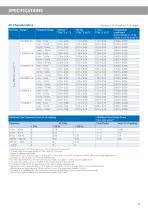
SPECIFICATIONS AC Characteristics Frequency Range Accuracy ± (% of reading + % of range) 1) Additional Low Frequency Errors (% of reading) Frequency 10 Hz – 20 Hz 20 Hz – 40 Hz 40 Hz – 100 Hz 100 Hz – 200 Hz 200 Hz – 1 kHz > 1 kHz Additional Crest Factor Errors (non-sine wave) 7) Crest Factor > 200 Hz – – 0.73 0.22 0.18 0 Specifications are for 90-minute warm-up, > 3 Hz ac filter and sine wave input. 10 % over range on all ranges except ACV 750 V and ACI 10 A ranges. Relative to calibration standards. 4) Specifications are for sine wave input > 5 % of range. For inputs within 1% and 5 % of range...
Open the catalog to page 9
SPECIFICATIONS Frequency and Period Characteristics Frequency Range Frequency, Period Temperature coefficient 0 °C to (TCAL °C - 5 °C) (TCAL °C +5 °C) to 50 °C 0.005 0.005 0.001 0.001 0.001 Specifications are for 90 minutes warm-up, using 1 s gate time. For frequency ≤ 300 kHz, the specification is the 10 % to 110 % of range of the AC input voltage. For frequency > 300 kHz, the specification is the 20 % to 110 % of range of the AC input voltage. The maximum input is limited to 750 V rms or 8 ×10⁷ Volts-Hz (whichever is less). The 200 mV range is full range input or input that is larger than the...
Open the catalog to page 10All Teledyne LeCroy Europe catalogs and technical brochures
 T3DSO4000L-HD
19 Pages
 WaveRunner 8000HD
20 Pages
 HDO6000B
20 Pages
 T3DSOH1000 /T3DSOH1000-ISO
15 Pages
 T3MIL50 Milli Ohm Meter
6 Pages
 T3PM1006 Digital Power Meter
8 Pages
 Current Probes
4 Pages
 WavePro HD
20 Pages
 WaveRunner 9000
20 Pages
 PeRT3 Phoenix System
16 Pages
 DDR Test Suite
12 Pages
 LabMaster 10 Zi-A
28 Pages
 WaveRunner 8000
24 Pages
 wavesurfer 510
20 Pages
 MDA800 Motor Drive Analyzers
8 Pages
 MIPI M-PHY Protocol Analyzer
4 Pages
 Transmission Line Probes
2 Pages
 WaveSurfer 10 Oscilloscope
12 Pages
 Summit T24 Analyzer
2 Pages
 SierraNet M168
4 Pages
 LabMaster 10 Zi Oscilloscopes
36 Pages
 LabMaster 9 Zi-A Oscilloscopes
36 Pages
 WaveMaster 8 Zi-A Oscilloscopes
36 Pages
 SDA 8 Zi-A Serial Data Analyzers
36 Pages
 DDA 8 Zi-A Disk Drive Analyzers
36 Pages
 WavePro 7 Zi-A Oscilloscopes
28 Pages
 SDA 7 Zi-A Serial Data Analyzers
28 Pages
 DDA 7 Zi-A Disk Drive Analyzers
28 Pages
 HRO 12-bit Oscilloscopes
8 Pages
 HDO8000 High Definition
20 Pages
 HDO6000 / HDO6000-MS High
20 Pages
 WaveRunner 6 Zi Oscilloscopes
28 Pages


Archived catalogs
 HDO4000 / HDO4000-MS High
16 Pages
 Summit T3-16 Analyzer
2 Pages
 Voyager M3i
8 Pages
 WaveSurfer 3000 Oscilloscopes
12 Pages
 WaveJet 300A Oscilloscopes
8 Pages
 Differential Amplifiers
2 Pages
 Current Probes
7 Pages
 HFP SERIES ACTIVE PROBES
4 Pages
 LeCroy Kibra 480 Analyzer
4 Pages
 Vehicle Bus Analyzers
2 Pages
 Signal Integrity Studio
4 Pages
 ArbStudio
8 Pages
 PeRT3 Eagle System
8 Pages
 SPARQ
SPARQ12 Pages
 LogicStudio
8 Pages


- Power supply unit
- DC power supply
- Concentration analyzer
- Automatic analyser
- Benchtop analyser
- Single-output power supply
- Portable analyzer
- Generator
- Digital analyzer
- Digital multimeter
- Power quality analyzer
- Programmable power supply
- Power meter
- DC/DC power supply
- High-performance analyzer
- Trace analyzer
- Electrical network analyzer
- 1000 V multimeter