 Website:
Teledyne Hastings Instruments
Group: Teledyne Technologies Incorporated
Catalog excerpts

TELEDYNE HASTINGS INSTRUMENTS INSTRUCTION MANUAL HFM-301/305/306 FLOW METERS HFC-303/307 FLOW CONTROLLERS
Open the catalog to page 1
Visit www.teledyne-hi.com for WEEE disposal guidance. The instruments described in this manual are available with multiple pin-outs. Ensure that all electrical connections are correct. The instruments described in this manual are designed for INDOOR use only. The instruments described in this manual are designed for Class 2 installations in accordance with IAW/IPC standards Hastings Instruments reserves the right to change or modify the design of its equipment without any obligation to provide notification of change or intent to change. Manual: 152-032015 301-305-306_303-307 Series
Open the catalog to page 2
General Information The Hastings 300 Series high range mass flow meters are designed to accurately measure mass flow at a range between 25 slm and 10000 slm. The Hastings 300 Series high range mass flow controllers are designed to accurately measure and control mass flow at a range between 25 slm and 2500 slm. These instruments are intrinsically linear and have an accuracy of better than ±1% F.S. (full scale). The Hastings 300 Series high range mass flow instruments determine the flow rate by measuring the rate of heat transfer between two wound thermal coils on a small diameter sensor...
Open the catalog to page 4
Optional 4-20 mA Current Output An option to the standard 0 - 5 VDC output is the 4 - 20 mA current output that is proportional to flow. The 4 - 20 mA signal is produced from the 0 - 5 VDC output of the flow meter. The current loop output is useful for remote applications where pickup noise could substantially affect the stability of the voltage output. The current loop signal replaces the voltage output on pin 6 of the “D” connector. The load must be less than 600. Failure to meet this condition will cause failure of the loop transmitter. The 4-20 mA I/O option can accept a current input....
Open the catalog to page 6
Operation This section contains the necessary steps to assist in getting a new flow meter/controller into operation as quickly and easily as possible. Please read the following thoroughly before attempting to install the instrument. 2.1. Receiving Inspection Carefully unpack the Hastings 300 Series instrument and any accessories that have also been ordered. Inspect for any obvious signs of damage to the shipment. Immediately advise the carrier who delivered the shipment if any damage is suspected. Check each component shipped with the packing list. Insure that all parts are present (i.e.,...
Open the catalog to page 7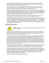
sulfur hexafluoride) or at high pressures (> 250 psig) the instrument must be installed horizontally. When mounted in a different orientation the instrument should be re-zeroed at zero flow with the system pressurized to the expected operating pressure. One of the smallest of the internal passageways in the 300 Series is the diameter of the sensor tube, which can be 0.026” (0.66 mm), 0.017” (0.43mm), or 0.014” (0.36mm), so the instrument requires adequate filtering of the gas supply to prevent blockage or clogging of the tube. The pressure regulator and the plumbing upstream must be of...
Open the catalog to page 8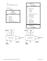
Do not use Do not use Do not use Do not use Signal Common Output 0-5 VDC (4-20mA) Signal Common Do not use Do not use +15 VDC Output 0-5 VDC (4-20mA) Signal Common Case Ground Valve Override -15 VDC External Input Signal Common Signal Common Set Point 0-5 VDC (4-20mA)
Open the catalog to page 9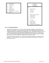
Case Ground Valve Override -15 VDC Do not use +15 VDC Signal Common External Input Set Point 0-5 VDC (4-20mA) Do not use Signal Common Do not use Do not use +15 VDC Output 0-5 VDC (4-20mA) Signal Common Case Ground Valve Override -15 VDC External Input Signal Common Signal Common Set Point 0-5 VDC (4-20mA) 2.6. 4 – 20 mA Connections The 300 Series flow meters have a 4 - 20 mA current output option available as an alternative to the standard 0 - 5 VDC output. This current output is useful for remote applications where noise pick-up could substantially affect the stability of the voltage...
Open the catalog to page 10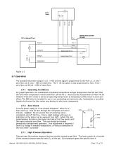
Hastings Flow Controller Pin-out H Analog Return 2.7. Operation The standard instrument output is a 0 - 5 VDC and the signal is proportional to the flow i.e., 0 volts = zero flow and 5 volts = 100% of rated flow. The 4 - 20 mA option is also proportional to flow, 4 mA = zero flow and 20 mA = 100% of rated flow. 2.7.1. Operating Conditions For proper operation, the combination of ambient temperature and gas temperature must be such that the flow meter temperature remains between -20 and 70°C. Most accurate measurement of flow will be obtained if the flow meter is zeroed at operating...
Open the catalog to page 11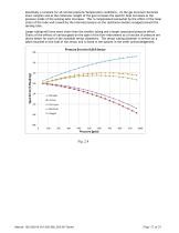
essentially a constant for all normal pressure/temperature conditions. As the gas structure becomes more complex and as the molecular weight of the gas increases the specific heat increases as the pressure inside of the sensing tube increases. This is compensated somewhat by the effect of the hoop strain of the tube wall caused by the internal pressure on the resistance heaters wrapped around the sensing tube. Larger tubing will have more strain than the smaller tubing and a larger associated pressure affect. Charts of the effects of various gases on the span of the flow instruments as a...
Open the catalog to page 12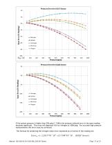
Pressure Error for 0.017 Sensor Pressure (psia) Pressure Error for 0.026 Sensor Pressure (psia) If the system pressure is higher than 250 psig (1.7 MPa) the pressure induced error in the span reading becomes significant. This error will approach 16% for nitrogen at 1000 psig. For accurate high pressure measurements this error must be corrected. The formula for predicting the nitrogen mean error expressed as a fraction of the reading are:
Open the catalog to page 13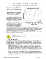
Error17 (7.1066 *10 8 ) P 2 (5.2403 *10 5 ) P, (0.017" Sensor ) Error14 (5.3091*10 8 ) P 2 (6.1278 *10 5 ) P, (0.014" Sensor ) Where P is the pressure in psig and Error is the fraction of the reading in error. The flow reading can be corrected as follows: Corrected Indication Indication * Error Where the Indication is the indicated flow and Error is the result of the previous formula (or read from charts above). 2.7.2. Vertical Mounting When operating at high pressure or with high density gases, the increased density of gas will cause natural convection to flow through the sensor tube, if...
Open the catalog to page 14All Teledyne Hastings Instruments catalogs and technical brochures
-
Service Overview
4 Pages
-
high flow meters & controllers
11 Pages
-
THCD-101 Product Bulletin
6 Pages
-
Thermocouple Gauge Tubes
10 Pages
-
VT & CVT Series
7 Pages
-
HFM-HFC
13 Pages
-
HFM-201/HFC-203
7 Pages
-
DAVC
5 Pages
-
HPM 4/5/6
4 Pages
-
DIGITAL 300 SERIES
8 Pages
-
Gauge Tubes
10 Pages
-
Rugedized Vacuum Gauge Tube
1 Pages
-
REFERENCE TUBES
2 Pages
-
DCVT & DVT
6 Pages
-
HFM-305 / HFC-307
4 Pages
-
HFM-301 / HFC-303
4 Pages
-
HFM-205 / HFC-207
5 Pages
-
HFM-200 LFE
5 Pages
-
HFM-200-LFE
5 Pages
-
Digital VT
6 Pages
-
HFM-D-301, 303, 305, 307
6 Pages
-
HFM-D-300/HFC-D-302
4 Pages
-
HFM-306
4 Pages
-
HFM-305/HFC-307
4 Pages
-
HFM-301/HFC-303
4 Pages
-
HFM-300/HFC-302
4 Pages
-
HFM-210/HFC-212
4 Pages
-
HFM-200/HFC-202
4 Pages
Archived catalogs
-
NALL SERIES
2 Pages
-
PowerPod-400
4 Pages
-
THCD—100
6 Pages
-
THCD-400
5 Pages
-
THCD—100
6 Pages
-
THCD-100
6 Pages
-
HPM-760S
4 Pages
-
Installation Accessories
2 Pages
-
Products
6 Pages
-
Flow Service Plan
1 Pages
-
THPS-400 / PowerPod 400
4 Pages
-
HFM-305A / HFC-307A
13 Pages
-
IGE-3000
2 Pages
-
Nall Mass Flow Meters
2 Pages
-
THCD -100
6 Pages
-
THPS-400
4 Pages
-
760 Plus
2 Pages
-
THI Product Overview
6 Pages
-
HFM-E-200/HFC-E-202
4 Pages


