
- Catalogs
- Teledyne DALSA
- PC2-Camlink

PC2-Camlink

PC2-Camlink
- Linescan Camera Support: Offers variable frame length acquisition and supports infinite vertical length frames with a shaft encoder and tick divider.
- Area Scan Camera Support: Capable of handling frame sizes up to 8K pixels by 8K lines.
- Visual Status LED: Provides visual status of acquisition and trigger detection, aiding installation.
- Extensive Trigger Interface Options: Includes inputs for Opto-coupled/TTL and LVDS triggers, with dual phase shaft encoder support.
- Parallel I/O Connector: Features an 8-bit in/out interface for easy connectivity with machine vision equipment.
The PC2-CamLink, part of DALSA’s PC2 Series, is designed for cost-sensitive applications and supports one monochrome, area, or line scan Base Camera Link camera. It simplifies system integration with visual status LEDs and provides direct power to cameras. The device is engineered within DALSA's Trigger-to-Imaging Reliability framework to ensure precise image acquisition.
The diagram outlines the PC2-CamLink's components, including the Acquisition Control Unit, Trigger Controller, and various interfaces for camera and host connectivity.
The Acquisition Control Unit (ACU) manages the image acquisition sequence, ensuring data integrity and signaling issues. The Trigger Controller validates trigger inputs and integrates a dual phase shaft encoder for accurate linescan processing. Visual status LEDs assist in installation and diagnostics.
Supports various channel scanning topologies and pixel depths up to 16-bit. Host transfers are managed via the PCI bus, with minimal CPU involvement due to a hardware scatter-gather engine.
Supported by DALSA’s Sapera LT and Imaging Foundation Class software libraries, enabling application development under Windows platforms. Sapera LT provides a unified API for versatile camera control and application development, while Sapera Processing offers advanced image processing tools.
Specifications last updated in February 2007. DALSA reserves the right to make changes without notice.
Catalog excerpts

K E Y B E N E F I T S Linescan Camera Support • Variable frame length acquisition • Supports infinite vertical length frame (8K pixels x infinite number o f line s ) • Shaft encoder with tick divide r Area Scan Camera Support • Frame size up to 8K pixels x 8K lines Visual Status LED • Facilitates installation by providing visual status of the acquisition • Separate indicator for trigger detection • Visible on PCI b r a c k e t Extensive Trigger Interface Options • Separate inputs for 2 Optocoupled/TTL and 2 LVDS triggers • Dual phase shaft encoder for line scan application s on 2 dedicated LVDS inputs Building y o u r machine vision system j u s t g o t easier Part of DALSA’s PC2 Series of frame grabbers, the PC2-CamLink™ is ideal for cost sensitive applications. Compatible with one monochrome, area or line scan Base Camera Link™ camera, the PC2-Camlink is a snap to interface to you r vision system thanks to the Camera Link standard and DALSA’s innovative visual status LED. When you connect the camera cable and external triggers the PC2-CamLink visual status LED s, mounted on the bracket, provide an immediate visual indication that all signals are present and active. To further simplify setup, the PC2- Camlink provides direct power (5V or 12V) to your camera. Parallel I/O Connector • 8-bit in/8-bit out registered interface to simplify connectivity to other ma chine vision equip m e n t • Pin-to-pin connector compatible with o the r PC2 Series and PC Vision c a rd s The PC2-CamLink has been engineered within DALSA's exacting Trigger- to- Imaging Reliability technology framework to control and monitor the entire image acquisition sequence.
Open the catalog to page 1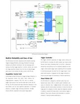
CamLink MDR-26 Base Connector Data Camera Control Camera Link Receiver LVDS UART Acquisition Visual Status LED Acquisition Control Unit Image Data Trigger Opto #1 Trigger Opto #2 Trigger LVDS #1 Trigger LVDS #2 Opto Coupler Trigger Controller LVDS Receiver Shaft Encoder #1 Shaft Encoder #2 Not Connected (factory default) l Host Computer PCI Base 32-bit/33MHz 3.3V/5V PC2-CamLink Functional Block Diagram Built-in Reliability and Ease of Use Trigger Controller The trigger controller supervises all trigger inputs coming into The PC2-CamLink has been engineered within DALSA’s exacting Trigger-to-Imaging...
Open the catalog to page 2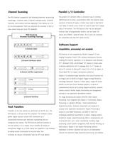
Channel Scanning The parallel I/O controller offers a convenient way to interface t o p o l o g y : 1-channel raster, 2-channel interleave pixels, 2-channel thePC2-CamLink to other controllers within the ma chine vision interlines, and 2-channel ha lf-line segmented. Pixel depths up to 1 6- system. It features 8 inputs, a strobe in put (used to latch the 8 bit a re also supported. Pixels can optionally be truncated to 8-bit to in put data), 8 outputs, and a strobe out (used to latch the 8 output ease camera setup an d lo w e r PCI bandwidth. data a t the receive r). The PC2-CamLink also h as...
Open the catalog to page 3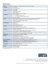
* Last updated February 2007 7075 Place Robert-Joncas, Suite 142, St-Laurent, Quebec, Canada H4M 2Z2 Visit us online @ www.imaging.com All trademarks are registered by their respective companies. DALSA reserves the right to make changes at any time without notice. C0DS-1182» DALSA 2007
Open the catalog to page 4All Teledyne DALSA catalogs and technical brochures
 Shad-o-Box HS
9 Pages
 Rad-icon datasheet
7 Pages
 Xcelera-CL+ PX8
2 Pages
 Remote RadEye Family
7 Pages
 Xineos 3131
2 Pages
 Xineos 2121
2 Pages


Archived catalogs
 Sapera APF
4 Pages
 Piranha HS 8k
2 Pages
 1M30
1M302 Pages
 BOA Pro
2 Pages
 Icon
Icon4 Pages
 Piranha3 16k Datasheet
2 Pages
 Pantera 22M04
2 Pages
 Spyder3 Color CL
2 Pages
 FT50M
FT50M2 Pages
 PC2-Comp Express
2 Pages
 IA-DJ
IA-DJ17 Pages
 Genie HC1024
2 Pages
 Genie C1280
2 Pages
 Falcon2 8M
2 Pages
 Falcon2 4M
2 Pages
 Falcon2 12M
2 Pages
 Falcon 4M60
2 Pages
 Falcon 4M60 Color
2 Pages
 BOA IDR
2 Pages
 Piranha HS 4K 110 kHz
2 Pages
 Xcelera-CL VX4
2 Pages
 Genie M1024
2 Pages
 Genie C1024
2 Pages
 Eclipse
2 Pages
 Falcon 4M30 Color
2 Pages
 Genie HM1400 / HM1400-XDR
2 Pages
 Falcon VGA300 HG
2 Pages
 SkiaGraph Product Family
2 Pages
 BOA
BOA2 Pages
 Spyder3 GigE
2 Pages
 FTF3021M
2 Pages
 IT-P1
IT-P12 Pages
 X64-AN Quad
4 Pages
 2009 products catalogue
13 Pages
- Digital imager
- Visible imager
- CMOS camera module
- Industrial camera module
- Monochrome camera module
- Image processing camera module
- Inspection imager
- High-speed camera module
- High-performance imager
- Machine vision video camera
- 3D imager
- X-ray detector
- CMOS image sensor
- X-ray flat panel detector
- Flat panel detector
- Digital flat panel detector
- High-resolution image sensor
- Time-integration camera