- Catalogs
- Tele Radio
- Tele Radio Lynx
Tele Radio Lynx
1 /64Pages

Tele Radio Lynx
1 /64Pages
Catalog excerpts

Tele Radio Lynx INSTALLATION MANUAL ENGLISH/ ESPAÑOL/ FRANÇAIS
Open the catalog to page 1
Stationary unit power supply 1 1 Connect the stationary unit 1 1 Place the stationary unit 1 1 Hand unit sleep mode 13 The stationary unit leds 15 Connections for digital inputs 17 Connections for Open Collector (OC) 18 Guarantee, servicing & repairs 20
Open the catalog to page 3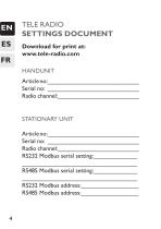
TELE RADIO SETTINGS DOCUMENT Download for print at: www.tele-radio.com HANDUNIT Article no:___________________________ Serial no: ___________________________ Radio channel:________________________ STATIONARY UNIT Article no:___________________________ Serial no: ___________________________ Radio channel:________________________ RS232 Modbus serial setting:_____________ __________________________________ RS485 Modbus serial setting:_____________ __________________________________ RS232 Modbus address:_________________ RS485 Modbus address:_________________
Open the catalog to page 4
Handunit LEDs 14. LED1 (red/green) 15. LED 2 (red) 16. LED 3 (red) 17. LED 4 (red) 18. LED 5 (red) 6 TX1-B buttons + button 4 button 5 button 6 TX1-C buttons + button 7 button 8
Open the catalog to page 6
Stationary unit Open Collectors
Open the catalog to page 7
Get starteD Read the instructions carefully before assembling, installing and programming the products. IT IS YOUR RESPONSIBILITY TO FIND OUT ABOUT THAT APPLY IN YOUR COUNTRY/REGION/COUNTY/STATE Tele Radio cannot be held responsible for any damage or other fault caused by a failure to follow the instructions. This may invalidate the warranty. If the manual does not cover all your needs, visit our website for FAQ and the latest information: www.tele-radio.com
Open the catalog to page 8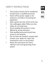
• This product should only be installed by licensed and/ or qualified personnel. • Switch off the power supply to the stationary unit before connecting the equipment. • Keep a good overview of the work area. • Use undamaged cables. Make sure that cables do not hang loose. • Avoid installing the product in areas affected by strong vibrations. • Only qualified personnel should have access to the handunit. • Do not leave the handunit unsupervised. • Contact your dealer for repair and maintenance work on the product. • Retain the instructions for future reference and re-programming of the system.
Open the catalog to page 9
THE SYSTEM Degree of protection: IP 65 Operating frequency: 2405-2480 MHz. Channels: Channel separation: 5 MHz. Antenna: Weight Interfaces: THE HANDUNIT Weight: TX1-A Internal 130 grams RS232, RS485, OC, Digital inputsjV*^ 120 grams 3 buttons 6 buttons
Open the catalog to page 10
STATIONARY UNIT POWER SUPPLY POWER SUPPLY CURRENT CONSUMPTION ES FR CONNECT THE STATIONARY UNIT Check that you have connected the power supply to the correct connection terminal. PLACE THE STATIONARY UNIT Well protected from wind, damp and water. With cable holders and vent plugs face down to prevent water from seeping in On a non-conductive surface for optimal performance. If possible, keep away from nearby WLAN, Bluetooth or other 2,4 GHz. equipment for optimal performance.
Open the catalog to page 11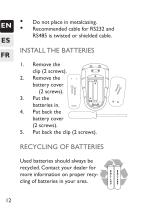
• Do not place in metalcasing. • Recommended cable for RS232 and RS485 is twisted or shielded cable. INSTALL THE BATTERIES Remove the clip (2 screws). Remove the battery cover (2 screws). Put the batteries in. Put back the battery cover (2 screws). Put back the clip (2 screws). Used batteries should always be recycled. Contact your dealer for more information on proper recycling of batteries in your area.
Open the catalog to page 12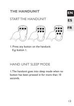
1. Press any button on the handunit. E.g. button 1. Hand unit Sleep Mode 1. The handunit goes into sleep mode when no button has been pressed in for more than 10 seconds.
Open the catalog to page 13
The Lynx system only controls the red/ green top LED 1 on the handunit. The function of LEDs 2-5 are determined by the design of the customer host system and therefore cannot be described here.
Open the catalog to page 14
The Stationary Unit The Stationary Unit LEDs S LED1 = green LED 2= yellow LED 3= red
Open the catalog to page 15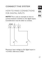
How to make connections for digital inputs NOTE! This is only an example on how to connect buttons/ switches to the digital inputs. Consideration must be taken to context. Maximum input voltage to the digital inputs is +3.3 VDC referred to GND. 17
Open the catalog to page 17
NOTE! This is to be viewed as an example on connections for the Open Collector outputs. Consideration must be taken to context. How to make connections for Open Collector (OC) outputs
Open the catalog to page 18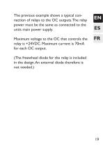
The previous example shows a typical connection of relays to the OC outputs. The relay power must be the same as connected to the units main power supply. Maximum voltage to the OC that controls the relay is +24VDC. Maximum current is 70mA for each OC output. (The freewheel diode for the relay is included in the design. An external diode therefore is not needed.)
Open the catalog to page 19
GUARANTEE Tele Radio’s products are covered by a guarantee against material, construction or manufacturing faults. During the guarantee period Tele Radio may replace the product or faulty parts with new ones. Work under warranty must be carried out by Tele Radio or by an authorized service centre specified by Tele Radio. The following faults are not covered by the warranty: • Faults resulting from normal wear and tear. • Parts of a consumable nature. • Products that have been subject to unauthorized modifications. • Faults resulting from incorrect installation or use. • Damp or water damage....
Open the catalog to page 20
you contact a dealer about a complaint or service issue: Name of the system, model and a description of the problem. If you need to return a product, the invoice number and delivery date should be included. FR OPERATING GUIDELINES • Keep the product in a dry, clean place. • Make sure that contacts and antennas are kept clean. • Wipe off dust using a slightly damp, clean cloth. • Never use cleaning solutions or high-pressure water. This product complies with current European directives and standards. “Declaration of Conformity” can be downloaded from: www.tele-radio.com.
Open the catalog to page 21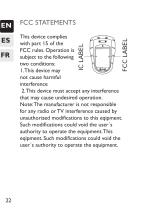
FCC STATEMENTS This device complies with part 15 of the _| FCC rules. Operation is subject to the following two conditions: 1. This device may not cause harmful interference 2. This device must accept any interference that may cause undesired operation. Note: The manufacturer is not responsible for any radio or TV interference caused by unauthorized modifications to this eqipment. Such modifications could void the user's authority to operate the equipment. This eqipment. Such modifications could void the user's authority to operate the equipment.
Open the catalog to page 22All Tele Radio catalogs and technical brochures
 Safety instruction sheet (R2-01)
3 Pages
 Panther Line
4 Pages
 Panther PLd
4 Pages
 TEQ Line - Waist Belt
6 Pages
Archived catalogs
 Exster - TEQ Line
6 Pages
 Our Worldwide Network
2 Pages
 Tele Radio Product Line
2 Pages
 Tiger Line
4 Pages
 T20/T60
4 Pages
 Panther Winch Kits
4 Pages
 PN-T19-2
1 Page
 PN-R8-6
1 Page
 T20/T60RX-03ADL
1 Page
 1/4-433K5
1 Page
 D7-02
D7-021 Page
 TG-T9-2
1 Page
 TG-T9-1
1 Page
 TG-T11-4
1 Page
 TG-T11-5
1 Page
 TG-T14-7
1 Page
 T24-01
1 Page
 TS26-02
1 Page
 T26-03
1 Page
 R20-01
1 Page
 R21-01
1 Page
 TG-T9-12
1 Page
 TG-T9-22
1 Page
 PN-T7-16
1 Page
 LX-T1-1
1 Page
 T20TX-01NKL
1 Page
 PN-T21-10
1 Page
 T60TX-03STL
1 Page
 R27-01
1 Page
 TG-T12-24
1 Page
 SupraTEQ TW77
1 Page
 PN-T21-10
1 Page
 T60-T8-51
1 Page
 T60-T8-52
1 Page
 T60-T8-53
1 Page
 CO-TX-MNL1
1 Page
 Tiger G2
1 Page
 LX-T1-3 TX1-C
1 Page
 LX-T1-2 TX1-B
1 Page
 datasheet
1 Page
 System T20
45 Pages

- Wireless remote control
- Industrial remote control
- Remote control with buttons
- IP65 remote control
- Crane remote control
- Radio receiver
- On/off remote control
- Joystick remote control
- Safety remote control
- Rechargeable remote control
- Compact remote control
- Remote control receiver
- Lithium remote control
- Compact receiver
- Rugged remote control
- Industrial receiver
- Remote control with toggle switch
- Rugged receiver
- Remote control with integrated display
- Serial receiver