Amplifier
1 /10Pages

Amplifier
1 /10Pages
Catalog excerpts

AC Servo Am plifiers ESDA Drivers ESDA Drivers Specification Driver Model No. Maximum Peak Current (A) Maximum Rated Current (A) Motor Power Power Source Encoder Vibration Control Mode Input Type Max. Input Freq. Electronic Gear Ratio Input Ripple Filtering In Position Range JOG Alam History Encoder Output < 1.5G Position A-B Phase, Up-Down Pulse, or Direction Pulse 500kpps 1/127≤A/B≤127 (A&B: 1 ~ 10000) Time Constant = 0~ 10000 ms 0 ~ 32767 Pulses Panel 10 Alarm Mumbers are Stroed A, B, Z Phase Line Drive Output Display D/I D/O Communication Weight (KG) 5-digit LED display, 4 button Servo ON, Pulse Input Inhibit, Clear Error Counter Alarm, In Position RS-232C for User's Parameter Setting and Status Monitoring 1.1 1.4 1.85 1.85
Open the catalog to page 1
Driver Model No. Maximum Peak Current (A) Maximum Rated Current (A) Motor Power Power Source Encoder Vibration Control Mode Input Tupe Preset (Internal Speed) Linear Acceleration/Deceleration Zero Speed Determination Specified Speed Reached Servo Lock Internal Torque JOG Alam Encoder Output Display D/I D/O Communication Weight (KG) <0.5G Speed 0 ~ ± 10V (Looking at the Motor Shaft, +V = CCW) Three Preset Speeds Available Through Defining User's Parameter Enable/Disable: May Be Defined by User's Parameter. When Enabled, the Time Constant May be Defined by User's Parameter Between 10ms ~ 10000ms...
Open the catalog to page 2
Power For Input Port Clear Error Countor Pulse Inhibit pulse/ Direction Reoeneration Resistor EFERENCE VOLTAGE SIGNAL GROUND BRAKE INTERLOCK+ BRAKE INTERLOCK- Regeneration Resistor
Open the catalog to page 3
Motor Power Cable Connection Specification General Military Connector (With Mechanical Brake) Pin No. Lead Color Signal Pin No. Lead Color 1 Red U B Red 2 White V G White 3 Black W E Black 4 Green FG C Green DC+24V A Mechanical Brake Mechanical 0V F Control Wire Brake Military Connector (Without Mechanical Brake) Pin No. Lead Color Signal A Red U B White V C Black W D Green FG CN2 (Encoder Connection Specifications) - ESDA Power Output (-) Encoder B Phase Input Encoder B Phase Input Encoder A Phase Input Shielded Twisted-Pair Cables 9812 Whithorn Dr., Houston, TX 77095, Phone: 281.855.2218, Fax:...
Open the catalog to page 4
AC Servo Am plifiers TSTA Drivers TSTA Drivers Main Circuit R, S, T Input Power Supply Control Circuit R, S Weight(KG) Cooling System Control of Main Circuit Control Mode Encoder Resolution Feedback Resolution Command Source Model No. Input Pulse TSTA20C TSTA30C TSTA50D TSTA75D Single/Three Phase 200-230Vac Three Phase 200~300Vac +10%~-15% 5/60 Hz +/-5% +10%~-15% 5/60 Hz +/-5% Single/Three Phase 200-230Vac +10%~-15% 5/60 Hz +/-5% 1.9 1.9 2.4 4.7 Natural Air Circulation Fan Cooling SVPWM Control Position (External or Internal), Speed, Torque, Position/Speed, Speed/Torque, Position/Torque 2000ppr/8000ppr;...
Open the catalog to page 5
Voltage Command Input Impedance Torque Time Constant Position Output Type Encoder Ratio Output Torque Control Mode Optional input to 13 Ports Input Digital Fix Output to 4 Ports Optional input to 4 Output Ports Analog Monitoring Output Protection Function Commnication Interface 0~+/-10Vdc/0 ~ +/- 300% 10kΩ Time Constant 0~50sec A, B, Z line drive output 1~8192 encoder ratio (any arbitrary value) servo on, alarm reset, P/PI switching, forward/reverse inhibit limit, external torque limit, external torque limit, pulse deviation clear, servo lock, emergency stop, speed command selection, control...
Open the catalog to page 6
Cscm4 Tnrqu« LimH fILMT) Akin Char |*LHSj PoaL Command Lmtt^lHj Rufr<-*: '/MITT, (lrra.rnitig
Open the catalog to page 7
Pl'PSwlEli (PCNT) Alaij Clear lALRSj
Open the catalog to page 8
Jlarn Ctea-iALHS) Spnnu" ISI'U') tliPW Grumidhg J- brewer Output A friaw Encode! OIII|IIIL'>\ PtuuM J-Encoder OulpuUB ^van CO-11 Srr.rr h . ril'Jilm Code!
Open the catalog to page 9
Motor Power Cable Connection Specification General Pin No. Lead Color 1 Red 2 White 3 Black 4 Green Mechanical Brake Control Wire Military Connector (With Mechanical Brake) Pin No. Lead Color B Red G White E Black C Green A Mechanical F Brake Military Connector (Without Mechanical Brake) Pin No. Lead Color Signal A Red U B White V C Black W D Green FG CN2 (Encoder Connection Specifications) - ESDA Lead Color 7T (Tamagawa) Shielded Twisted-Pair Cables Power Output (+) Power Output (-) Encoder A Phase Input Encoder B Phase Input Wiring Diagram Encoder B Phase Input 9812 Whithorn Dr., Houston, TX...
Open the catalog to page 10All Telco catalogs and technical brochures
 IntelliGreen® 48
1 Page
 IntelliGreen® 100
1 Page
 comGreenAire® UB
1 Page
 FAN & BLOWERS
1 Page
 TELCO GEAR
6 Pages
 ECM Motors
1 Page
 DC Motor - PMDC
1 Page
 DC Motors - Coreless
2 Pages
 BLDC Vs. PMDC
2 Pages
 BLDC Motor - NEMA
1 Page
 BLDC Motor - Micro
1 Page
 AC Motor
1 Page
 Line Cord (Assembly)
2 Pages
 Modular Jack
3 Pages
 ECM Pump
1 Page
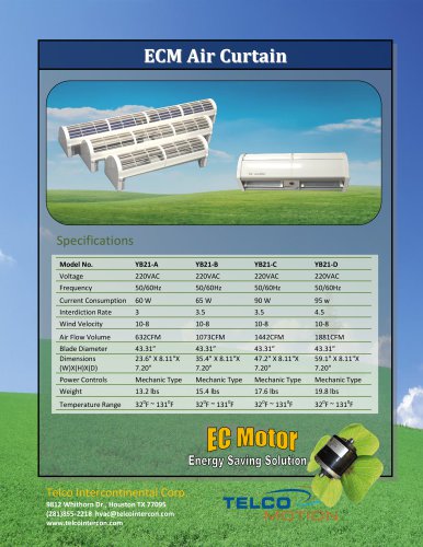 ECM Air Curtain
1 Page
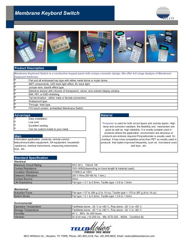 Membrane Switch
1 Page
 Touch Screen
9 Pages
 Gearbox
8 Pages
 DC Fan
2 Pages
 AC Fan
1 Page
 Non-Captive Shaft Actuator
2 Pages
 External Actuator
2 Pages
 Linear Actuator
7 Pages
 Parallel Shaft Gearmotor
25 Pages
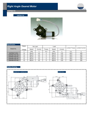 Right Angle Gearmotor
25 Pages
 NEMA Frame AC
26 Pages
 PM Stepper
50 Pages
 NEMA BLDC
5 Pages
 Outer Rotor Motor
7 Pages
 Brushless DC Motor
1 Page
 Axial Fan Motor
1 Page
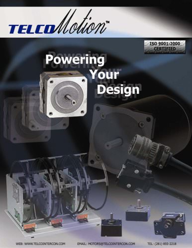 TelcoMotion
4 Pages
 Right Angle Gearmotor
25 Pages
 Industrial Grade PMDC
5 Pages
 PSC Motor
24 Pages


Archived catalogs
 Micro DC Gearmotor Catalog
11 Pages
 Coreless DC Motor Catalog
6 Pages
 Micro Brushless DC Motors
13 Pages


- Electromotor
- Compressor stage
- DC electromotor
- Air compressor
- Synchronous motor
- Stationary compressor
- Alternating current motor
- Multipole motor
- Industrial compressor
- Electric gearmotor
- Asynchronous motor
- Electromotor for industrial applications
- EC motor
- Three-phase motor
- 24 V motor
- Direct current gear-motor
- Servo-motor
- 4-pole motor
- Air blower
- 2-pole motor