6 series mso
1 /71Pages

6 series mso
1 /71Pages
Catalog excerpts

6 Series MSO Mixed Signal Oscilloscope Datasheet
Open the catalog to page 1
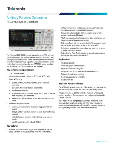
Optional analysis Input channels 4 FlexChannel® inputs Each FlexChannel provides: • • One analog signal that can be displayed as a waveform view, a spectral view, or both simultaneously Eight digital logic inputs with TLP058 logic probe Bandwidth (all analog channels) • Sample rate (all analog / digital channels) • • Optional serial bus trigger, decode, and analysis • Record length (all analog / digital channels) • • Advanced Jitter and Eye Diagram Analysis User-defined filtering Advanced Spectrum View RF vs. Time traces (magnitude, frequency, phase) Digital Power Management Mask/Limit Testing...
Open the catalog to page 2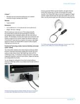
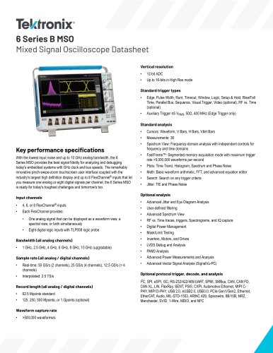
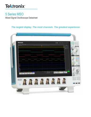
Remotely view and control the oscilloscope over a network connection through a standard web browser Previous-generation MSOs required tradeoffs, with digital channels having lower sample rates or shorter record lengths than analog channels. The 6 Series MSO offers a new level of integration of digital channels. Digital channels share the same high sample rate (up to 25 GS/s), and long record length (up to 250 M points) as analog channels. With the lowest input noise and up to 8 GHz analog bandwidth, the 6 Series MSO provides the best signal fidelity for analyzing and debugging today's embedded...
Open the catalog to page 3
Channel 2 has a TLP058 Logic Probe connected to the eight inputs of a DAC. Notice the green and blue color coding, where ones are green and zeros are blue. Another TLP058 Logic Probe on Channel 3 is probing the SPI bus driving the DAC. The white edges indicate higher frequency information is available by either zooming in or moving to a faster sweep speed on the next acquisition.
Open the catalog to page 4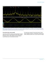
Beyond just analog and digital, FlexChannel inputs include Spectrum View. This Tektronix-patented technology enables you to simultaneously view both analog and spectral views of all your analog signals, with independent controls in each domain. For the first time ever, oscilloscope-based frequency-domain analysis is as easy as using a spectrum analyzer while retaining the ability to correlate frequency-domain activity with other time-domain phenomena. Unprecedented signal viewing capability The stunning 15.6" (396 mm) display in the 6 Series MSO is the largest display in the industry. It is also...
Open the catalog to page 5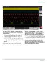
Stacked display mode enables easy visibility of all waveforms while maintaining maximum ADC resolution on each input for the most accurate measurements. The 6 Series MSO offers a revolutionary new Stacked display mode. Historically, scopes have overlaid all waveforms in the same graticule, forcing difficult tradeoffs: • To make each waveform visible, you vertically scale and position each waveform so that they don't overlap. Each waveform uses a small percentage of the available ADC range, leading to less accurate measurements. For measurement accuracy, you vertically scale and position each...
Open the catalog to page 6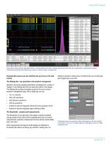
Viewing three analog channels, eight digital channels, a decoded serial bus waveform, decoded serial packet results table, four measurements, a measurement histogram, measurements results table with statistics and a search on serial bus events - simultaneously! Exceptionally easy-to-use user interface lets you focus on the task at hand additional waveform viewing area, the Results Bar can be dismissed and brought back at any time. The Settings Bar - key parameters and waveform management Waveform and scope operating parameters are displayed in a series of “badges” in the Settings Bar that runs...
Open the catalog to page 7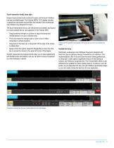
Touch interaction finally done right Scopes have included touch screens for years, but the touch interface has been an afterthought. The 6 Series MSO's 15.6" display includes a capacitive touchscreen and provides the industry's first oscilloscope user interface truly designed for touch. The touch interactions that you use with phones and tablets, and expect in a touch enabled device, are supported in the 6 Series MSO. • • • • Drag waveforms left/right or up/down to adjust horizontal and vertical position or to pan a zoomed view Pinch and expand to change scale or zoom in/out in either horizontal...
Open the catalog to page 8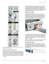
Color-coded LED light rings indicate trigger source and vertical scale/ position knob assignments. Large, dedicated Run/ Stop and Single Sequence buttons are placed prominently in the upper right, and other functions like Force Trigger, Trigger Slope, Trigger Mode, Default Setup, Auto-set and Quick-save functions are all available using dedicated front panel buttons. Windows or not - you choose The 6 Series MSO offers you the choice of whether to include a Microsoft Windows™ operating system. Opening an access panel on the bottom of the instrument reveals a connection for a solid state drive...
Open the catalog to page 9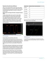
Experience the performance difference Sample rate Number of bits of vertical resolution With up to 8 GHz analog bandwidth, 25 GS/s sample rates, standard 62.5 Mpts record length and a 12-bit analog to digital converter (ADC), the 6 Series MSO has the performance you need to capture waveforms with the best possible signal fidelity and resolution for seeing small waveform details. Digital Phosphor technology with FastAcq™ high-speed waveform capture To debug a design problem, first you must know it exists. Digital phosphor technology with FastAcq provides you with fast insight into the real operation...
Open the catalog to page 10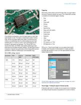
Triggering Discovering a device fault is only the first step. Next, you must capture the event of interest to identify root cause. The 6 Series MSO provides a complete set of advanced triggers, including: A key attribute to being able to view fine signal details on small, highspeed signals is noise. The higher a measurement systems' intrinsic noise, the less true signal detail will be visible. This becomes more critical on an oscilloscope when the vertical settings are set to high sensitivity (like ≤ 10 mV/div) in order to view small signals that are prevalent in high-speed bus topologies. The...
Open the catalog to page 11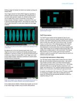
Defining a trigger that isolates the desired event speeds up debug and analysis efforts. Visual Trigger extends the 6 Series MSO's triggering capabilities by scanning through all waveform acquisitions and comparing them to on-screen areas (geometric shapes). An unlimited number of areas can be created using a mouse or touchscreen, and a variety of shapes (triangles, rectangles, hexagons, or trapezoids) can be used to specify the desired trigger behavior. Once shapes are created, they can be edited interactively to create custom shapes and ideal trigger conditions. Boolean logic trigger qualification....
Open the catalog to page 12All Tektronix catalogs and technical brochures
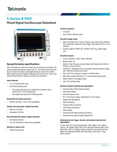 5 Series B MSO
67 Pages
 5 Series MSO Low Profile
40 Pages
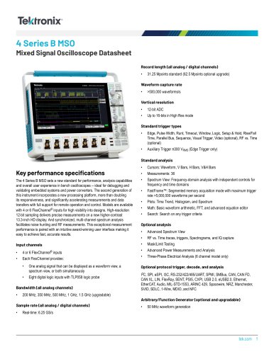 4 Series B MSO
55 Pages
 3 Series MDO
35 Pages
 6 Series B MSO
76 Pages
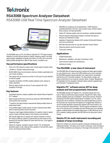
 RSA306B
29 Pages
 TBS2000B Series
18 Pages
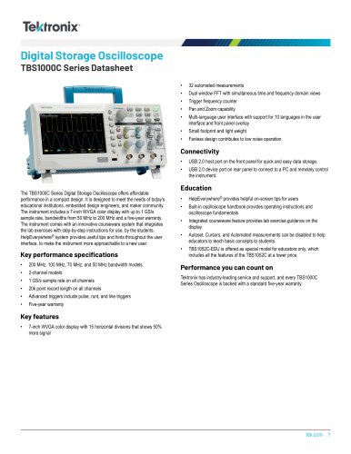 TBS1000C Series
15 Pages
 5 Series
40 Pages
 6 Series
41 Pages
 FCA3000 and FCA3100 Series
8 Pages


Archived catalogs
 5 Series MSO Low Profile
39 Pages
 MPEG Test Systems MTS4000
12 Pages
 5 Series MSO
73 Pages
 5 Series MSO 2022
67 Pages


- Power supply unit
- DC power supply
- Management software solution
- Automation software solution
- Analysis software solution
- Windows software
- Automatic analyser
- Real-time software
- Cloud-based software
- Control software
- Benchtop analyser
- Single-output power supply
- Switching power supply
- Power supply for industrial applications
- Industrial software
- Portable analyzer
- Interface software
- Measurement software
- Generator
- Power supply with overload protection