
Catalog excerpts

Datasheet TBS01A SDI-12 / UART Interface Module The TBS01A SDI-12 / UART module is a bi-directional interface for the conversion of commands and data into SDI-12 format and vice versa. The module is Plug and Play, targeting cost sensitive data logging applications. It offers low current consumption, small footprint and easy integration into products which require a SDI-12 interface. The user does not need to invest any time for the implementation of the SDI-12 protocoll and interface hardware, as this is an integral part of the SDI-12 UART interface module. The TB01 contains all the necessary components of a complete SDI-12 interface. It includes a SDI-12 front-end, controller, crystal and passive components. The TBS01A has been engineered specifically for applications where cost, performance, time to market and ease of integration are prime considerations. The TBS01A is a functionally and mechanically compatible replacement of the TBS01 module. Features SDI-12 / UART Interface SDI-12 Standard V1.3 Selectable data rate: 4800, 9600, 19200, 38400 Baud Plug and Play Power Down Mode 3.3V UART interface 3.3V, 5V supply voltage 23 mm x 18 mm SMT module 2.3 mm module thickness Operating Temperature Range: -40°C - +85°C Target Applications SDI-12 Data Logger SDI-12 / RS232 Interface © 2014 Tekbox Digital Solutions 29/29 Yen The, F2 | Q. Tan Binh | Ho Chi Minh City | Tel +84 (83)5471340 | E-mail office@
Open the catalog to page 1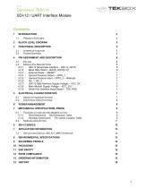
V1.2 Datasheet TBS01A SDI-12 / UART Interface Module 4.2.2 Baud Rate Select - BAUD_RATE[ 1:0] 6 4.2.4 General Purpose Output - GPIO_1 7 4.2.5 General Purpose Input - GPIO_2 - WakeUp 7 4.2.7 SDI-12 Data Interface Supply Voltage - VCC_5V 7 4.2.8 Main Module Supply Voltage - VCC_3V3 7 4.2.9 Serial Port Interface Input/Output - TXD, RXD 7 5.1 Package outline and recommend layout 9 5.1.1 Pad Dimensions Pad Dimension Table 9 5.1.2 Package Dimensions Pin centre Location Table 9 7.1 Application Circuit, SDI-12 / UART Interface 13
Open the catalog to page 2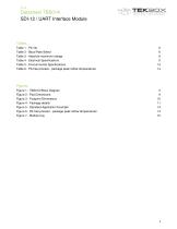
V1.2 Datasheet TBS01A SDI-12 / UART Interface Module Tables Table 2 - Baud Rate Select 6 Table 3 - Absolute maximum ratings 8 Table 4 - Electrical Specifications 9 Table 5 - Environmental Specifications 13 Table 6 - Pb-free process - package peak reflow temperatures 14 Figure 1 - TBS01A Block Diagram 5 Figure 3 - Footprint Dimensions 10 Figure 4 - Package details 11 Figure 5 - Standard Application Example 13 Figure 6 - Pb-free process - package peak reflow temperatures 14 Figure 7 - Module tray 15
Open the catalog to page 3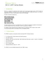
V1.2 Datasheet TBS01A SDI-12 / UART Interface Module 1 Introduction SDI-12 is a standard for interfacing data recorders with microprocessor-based sensors. SDI-12 stands for serial/digital interface at 1200 baud. It can connect multiple sensors with a single data recorder on one cable. It supports up to 60 meters of cable between a sensor and a data logger. The SDI-12 standard is prepared by SDI-12 Support Group (Technical Committee) 165 East 500 South River Heights, Utah 435-752-4200 435-752-1691 (FAX) http://www.sdi-12.org The latest standard is version V1.3 and dates from July 18th, 2005....
Open the catalog to page 4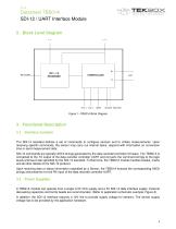
Datasheet TBS01A SDI-12 / UART Interface Module 2 Block Level Diagram Figure 1 –TBS01A Block Diagram 3 Functional Description 3.1 Interface function The SDI-12 standard defines a set of commands to configure sensors and to initiate measurements. Upon receiving specific commands, the sensor may carry out internal tasks, respond with information on conversion time or send measurement data. SDI-12 commands are typically ASCII strings generated by the data recorder/controller firmware. The TBS01A is connected to the TX output of the data recorder controller UART and converts the command strings...
Open the catalog to page 5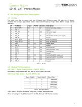
V1.2 Datasheet TBS01A SDI-12 / UART Interface Module4 Pin Assignment and Description 4.1 Pin List This table shows the pin names, their type (DI-digital input, DO-digital output, OD-open drain, P-power), whenever they have pull-up/pull-down when in input mode (PU-pull-up, PD-pull-down), the I/O voltage, and the description. Table 2 - Baud Rate Select UART setting : Baud rate, 8 databits, parity none, 1 stopbit, handshake none. When connecting any Baud Rate Select Pin to VCC_3V3, use 100K Pull Up resistors.
Open the catalog to page 6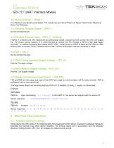
Datasheet TBS01A SDI-12 / UART Interface Module 4.2.3 External Reset – /RESET The /Reset pin can be left unconnected. The module has an internal Power On Reset, Power Down Reset and Brown Out Detection. 4.2.4 General Purpose Output – GPIO_1 Do not connect this pin. 4.2.5 General Purpose Input – GPIO_2 – WakeUp If GPIO_2 is tied to 3.3V, the module will be continuously active, consuming 7mA current from the 3.3V supply line. For power saving reasons, it is recommended to control this Pin through a GPIO of the data logger controller. 1ms before accessing the module UART, GPIO_2 shall be set...
Open the catalog to page 7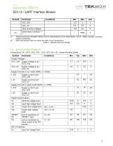
V1.2 Datasheet TBS01A SDI-12 / UART Interface Module Symbol (1) Tested according to MIL883C Method 3015.6 (Standardized Human Body Model: 100 pF, 1500Q, 3 pulses, protection related to substrate). (2) Static and dynamic latch-up values are valid at room temperature. Table 3 - Absolute maximum ratings Temperature TA = 20°C, VCC_3V3 = 3.3V, VCC_5V = 5V, unless otherwise stated
Open the catalog to page 8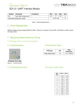
V1.2 Datasheet TBS01A SDI-12 / UART Interface Module Symbol Table 4 - Electrical Specifications 6 Power Management TBS01A wakes up upon setting GPIO2 to HIGH. If there is no activity on the UART, set GPIO2 to LOW to return into sleep mode. 5.1 Package outline and recommend layout Pin centre Location Table
Open the catalog to page 9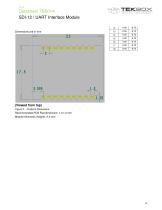
(Viewed from top) Figure 3 - Footprint Dimensions Recommended PCB Pad dimension: 1.2 x 2 mm Module thickness (height): 2.3 mm
Open the catalog to page 10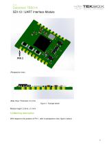
Datasheet TBS01A SDI-12 / UART Interface Module (Perspective view) (Side View; Thickness: 2.3 mm) Figure 4 - Package details 5.2 Marking description With respect to the position of Pin 1, refer to perspective view, figure 4 above
Open the catalog to page 11
Datasheet TBS01A SDI-12 / UART Interface Module 6 SDI-12 Basics SDI-12 is a serial data communication standard for interfacing multiple sensors with a data recorder The SDI-12 uses a shared bus with 3 wires: power (12V), data, ground Data rate: 1200 baud Each sensor at the bus gets a unique address which is in the range ASCII [0-9, a-z, A-Z]. The default address of every sensor is ASCII[0]. When setting up a SDI-12 sensor network, every sensor needs to be configured with a unique address. This can be done using the “Change Address Command”. A sensor typically can measure one or more...
Open the catalog to page 12All TEKBOX catalogs and technical brochures
-
Q&A Open TEM Cells
4 Pages
-
SDI-12 / ANALOG Interface Module
25 Pages


