Q&A Open TEM Cells
1 /4Pages

Q&A Open TEM Cells
1 /4Pages
Catalog excerpts

Q&A Tekbox Open TEM Cells 1 What is the usable volume of Tekbox TEM Cells? The TBTC1 TEM cell has a septum height of 5cm and a septum width of 13cm. The flat section of the bottom plane has an area of 20cm x 20 cm. The TBTC1 was designed to be a small device, that easily fits on a lab desk and which typically would be used to investigate spurious signals emitted by small to medium size PCB assemblies. If the purpose is rather checking frequencies than levels of spurious signals, basically any DUT that would physically fit can be inserted into the TEM cell. For safety reason, an insulation distance of 0.5 cm to 1cm to the bottom and 1cm to the septum is recommended. Thus the usable height of a DUT would be limited to 3-4 cm. A consequence of a large DUT would be a degradation of the impedance matching of the TEM cell. Tests with large DUTs in the TBTC1 have shown the S11 to vary between the value at empty state and -10dB. Consequently, a physically large DUT adds to the uncertainty when it comes to estimate equivalent spurious levels that would be measured using antennas in an anechoic chamber set up. The TBTC2 TEM cell has a septum height of 5cm and a septum width of 23cm. The flat section of the bottom plane has an area of 30cm x 30 cm. The TBTC2 was dimensioned according to specifications given in Annex E of the CISPR 25 specification. With respect to the maximum DUT size, similar considerations as mentioned above can be applied. However CISPR 25 specifies an allowed working region which is 18cm x 18cm and located as per the screenshot below. Of course, similar considerations can be applied to the TBTC1. Picture 1 –: allowed working region – screenshot taken from CISPR25, Annex E
Open the catalog to page 1
Q&A Tekbox Open TEM Cells 2 Signal coupling - location dependency Setup: a piece of foam with a 3cm grid was placed into the TBTC2. In order to inject a signal into the TEM cell, a Tekbox E5 electric field probe was connected to the output of a RF Signal Generator and fed with 500 MHz, 0dBm. The signal level at the port of the TBTC2 was measured with a spectrum analyzer. Picture 2 – measurement setup
Open the catalog to page 2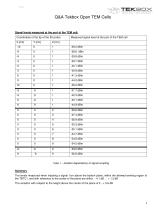
Q&A Tekbox Open TEM Cells rEKBOX DIGITAL SOLUTIONS Signal levels measured at the port of the TEM cell: Table 1 - location dependency of signal coupling Summary The levels measured when injecting a signal 1cm above the bottom plane, within the allowed working region of the TBTC1, and with reference to the center of the plane are within - 4.1 dB ... + 1.3 dB The variation with respect to the height above the center of the plane is 0...+ 5.6 dB
Open the catalog to page 3
Q&A Tekbox Open TEM Cells rEKBOX DIGITAL SOLUTIONS
Open the catalog to page 4All TEKBOX catalogs and technical brochures
 SDI-12 / ANALOG Interface Module
25 Pages


- Temperature probe
- Measuring device
- Test cabinet
- Resistance temperature sensor
- IO module
- Level probe
- Liquid level sensor
- Terminal box
- Analog I/O
- Pressure probe
- Signal amplifying integrated circuit
- Wall-mounted splice box
- Solderless terminal
- Humidity and temperature probe
- Analog IO module
- Membrane pressure sensor
- Polymer junction box
- DIN rail converter
- Power amplifying integrated circuit