Catalog excerpts
INSTRUCTION MANUAL operates with ISO9001 certified quality system TECSYSTEM S.r.l. 20094 Corsico (MI) Tel.: +39-024581861 Fax: +39-0248600783 “Translations of the original instructions
Open the catalog to page 1
INTRODUCTION First of all we wish to thank you for choosing to use a TECSYSTEM product and recommend you read this instruction manual carefully: You will understand the use of the equipment and therefore be able to take advantage of all its functions. ATTENTION! THIS MANUAL IS VALID AND COMPLETE FOR THE UNITS: NT511-NT511 MODBUS INSIDE NT511 AD CONTENTS PAGE 1) SAFETY REQUIREMENTS OPERATING PROGRAM CONTROL NOTES ON SCAN AND MAN FUNCTIONS ALARM RELAY SILENCING POWER SUPPLY
Open the catalog to page 2
8) RS485 MODBUS (only for NT511 Modbus or AD) INTRODUCTION TO THE MODBUS INSIDE MODULE OPERATING NOTES DATA TRANSMISSION ON MODBUS NETWORK DATA FRAME DATA PACKET FUNCTION CODE NOTES FOR REMOTE PROGRAMMING ERROR CODES POLLING FREQUENCY MODBUS MAPPING TABLE
Open the catalog to page 3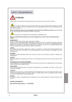
SAFETY REQUIREMENTS ATTENTION: Carefully read the manual before starting using the control unit. Keep the instructions for future reference. Do not open the device, touching any internal component can result in electric shock as voltages over 50 volts can be lethal. In order to reduce the risk of electric shock, do not disassemble the back of the device. Warranty shall be void if device is opened. Before connecting the device to the power supply, ensure that all the connections are correct. Always disconnect the unit from the supply before making any modification on the wiring. Any...
Open the catalog to page 4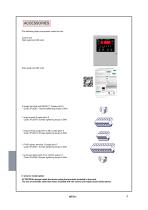
ACCESSORIES Tthe following object are present inside the box: Control unit Start guide and QR code Start guide and QR code 2 supply terminal and RS485 (*) 3 poles pitch 5 Code: 2PL0367 - Screws tightening torque 0.5Nm 1 relay terminal 9 poles pitch 5 Code: 2PL0376- Screws tightening torque 0.5Nm 1 relay terminal output M1 to M6 7 poles pitch 5 Code: 2PL0373- Screws tightening torque 0.5Nm 1 Pt100 sensor terminal 12 poles pitch 5 Code: 2PL0361- Screws tightening torque 0.5Nm 1 terminal 2 poles pitch 5 for 4.20mA output (*) Code: 2PL0364 -Screws tightening torque 0.5Nm (*) only for model...
Open the catalog to page 5
POWER SUPPLY
Open the catalog to page 6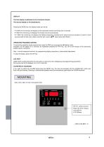
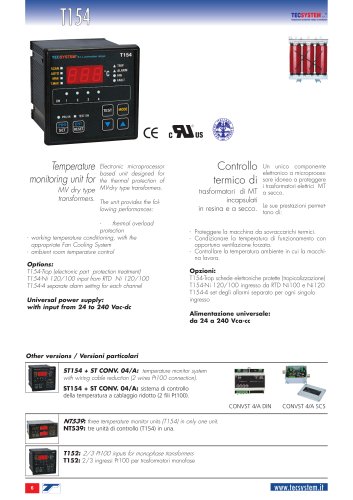
DISPLAY The first display is dedicated to the monitored channel. The second display to the temperatures. Pressing the MODE key, the display modes can be set: SCAN: the monitoring unit displays all the activated channels scanning every 2 seconds. HIGH: the monitoring unit displays the hottest channel automatically. T.MAX: the monitoring unit displays the highest temperature reached by the sensors and any situation of: alarm or fault occurred after the last reset. Select channels with cursors , reset values with RESET. OPERATING PROGRAM CONTROL To control the protection levels...
Open the catalog to page 9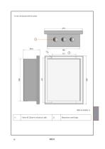
Fix the unit securely with the screws. 3 holes Ø 22mm for electrical cable
Open the catalog to page 10
Note: relay contact image in non-alarm condition, with the exception of the FAULT relay that chance his status: contacts 27-28 open (NO) contacts 26-28 closed (NC) fault condition identification. Read the Alarms and Ventilation paragraph on page 13 and see image of FAULT contact opening.
Open the catalog to page 11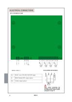
Note: before connecting the sensors to the control unit, read the Measurement signal transfer paragraph on page 16.
Open the catalog to page 12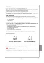
POWER SUPPLY The NT511 control unit has 230Vac ±10% 50-60Hz power supply (terminal 36-38). The ground must always be connected to terminal 37. When the unit is supplied directly by the secondary of the transformer to protect, it can be burnt out by strong overvoltages. This happens if the main switch is closed and the transformer has no load (blank test). The above-mentioned problems are much more evident when the 230 Vac voltage is taken directly from the transformerr secondary bars and there is a fixed capacitor battery to phase the transformer itself. If an existing control unit must be...
Open the catalog to page 13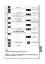
Fan cyclic test for 5 min. every “n” hours ATTENTION: We recommend you check the unit's programming before starting the device. The default parameters set by TECSYSTEM might not match your requirements. Programming the device is the end user's responsibility, the settings of the alarm thresholds and the enabling of the functions described in this manual must be checked (by a specialized engineer) according to the application and features of the system the control unit is installed on.
Open the catalog to page 15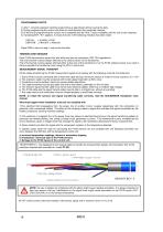
PROGRAMMING NOTES 1) After 1 minute's keyboard inactivity programming is abandoned without saving the data. 2) During programming the control unit does not control/protect the monitored machine. 3) At the end of programming the control unit is restarted and the FAULT relay is disabled until the unit is fully restarted. 4) If pressing ENT, “Err” appears, it means that one of the following mistakes has been made: ERR ALL. = ALARM ≥ TRIP ERR FAN = FAN-OFF ≥ FAN-ON Press PRG to return to step 1 and correct the data. TEMPERATURE SENSORS Each Pt100 thermometric sensor has one white and two red...
Open the catalog to page 16
TEMPERATURE SENSOR DIAGNOSTICS In case of failure or exceeded full scale value of one of the thermometric sensors installed on the machine to protect, the FAULT relay opens immediately with the relative warning of faulty sensor on the corresponding channel. Fcc indicates sensor short-circuited or minimum full scale value of the control unit exceeded -20°C Foc indicates sensor interrupted or maximum full scale value of the control unit exceeded 231°C To eliminate the message and reset the opening of the Fault contact, it is necessary to check the Pt100 connections and replace the faulty...
Open the catalog to page 17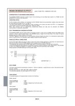
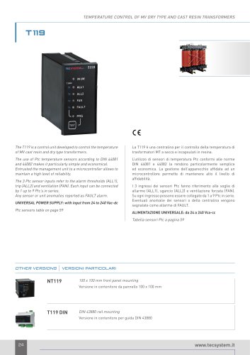
INTRODUCTION TO THE MODBUS INSIDE MODULE The MODBUS INSIDE expansion module is built in the monitoring unit and allows data transfer on a RS485 line with MODBUS RTU protocol, max 32 devices. OPERATING NOTES For the module to work correctly, it is necessary to set the RS485 network set-up parameters: address, baud rate, parity bit. See programming steps 22 to 27 on page 15. The serial communication of the temperature control monitoring unit is active only when the NT511 is in temperature control mode in one of the intended modes (Scan, High and T.Max). When other functions such as...
Open the catalog to page 18All TECSYSTEM srl catalogs and technical brochures
-
 NT935 AD
2 Pages
-
 TG180 – Fan series TG
9 Pages
-
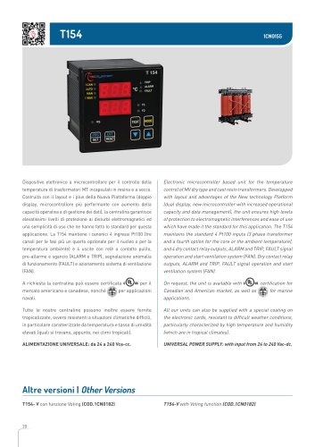
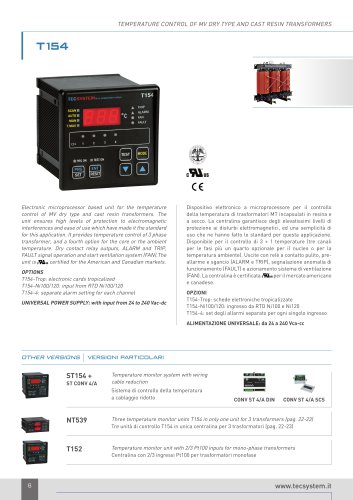
 T154
T1542 Pages
-
 PT73 -220
1 Pages
-
 VRT200
1 Pages
-
 NT935 ETH
2 Pages
-
 NT538 ETH
2 Pages
-
 NT935 IR AD
2 Pages
-
 Fan series TG
1 Pages
-
 VRT600
1 Pages
-
 T154 1CN0155
2 Pages
-
 new tpl 503 system
6 Pages
-
 MM453
MM45328 Pages
-
 NT538 WS
2 Pages
-
 NT935 WS
2 Pages
-
 Bars 1200-1800-3600
1 Pages
-
 NT511 AD specifiche tecniche
1 Pages
-
 MT4X4 D
1 Pages
-
 SISTEMA TPL503
3 Pages
-
 TPL 503 SYSTEM
6 Pages
-
 SCS-R 6/8 sensors wiring box
1 Pages
-
 PTSE Temperature sensor
1 Pages
-
 PTO Temperature sensor
1 Pages
-
 PTFE
PTFE1 Pages
-
 PTC Temperature sensor
1 Pages
-
 PTC Simulator
1 Pages
-
 PT100 SIMULATOR
1 Pages
-
 PT 73-220
1 Pages
-
 CTSE Extension cable
1 Pages
-
 CTES Extension cable
1 Pages
-
 T1048
T10484 Pages
-
 CONV ETH
1 Pages
-
 Bar 1200-1800-3600
1 Pages
-
 Bar 400-600-800
1 Pages
-
 TG 1000
1 Pages
-
 Fan series TG
1 Pages
-
 TTG SERIE
1 Pages
-
 PTSP
PTSP1 Pages
-
 TCK
TCK1 Pages
-
 Fan series TTG
1 Pages
-
 Bars 400-600-800
1 Pages
-
 SCS-R 3/4 sensors wiring box
1 Pages
-
 NT-511 AD
2 Pages
-
 VRT200
1 Pages
-
 VRT600
1 Pages
-
 SCS-R 6/8 sensors wiring box
1 Pages
-
 PTC Temperature sensor
1 Pages
-
 NT133-3
2 Pages
-
 T30
T302 Pages
-
 barra1200-1800-36003
1 Pages
-
 T-412
T-4122 Pages
-
 brochure TPL 503
6 Pages
-
 nt935
nt9353 Pages
-
 nt935-ir+tir409
3 Pages
-
 T154 Temperature control
2 Pages
-
 TG series
1 Pages
-
 TTG 240 - TTG 300
1 Pages
-
 TTG 360
1 Pages
-
 BARRA series
1 Pages
-
 NT538
NT5383 Pages
-
 NT935
NT9353 Pages
-
 NT539
NT5392 Pages
-
 NT511
NT5112 Pages
-
 TIR409 + NT935IR
3 Pages