Guide rail bending machine
1 /1Page
Guide rail bending machine
1 /1Page
Catalog excerpts
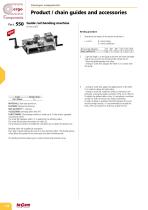
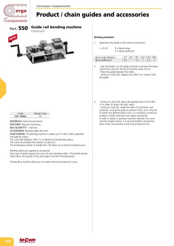
Conveyor components Part. 550 Guide rail bending machine(manual) Bending procedure 1. Determine the length of the section to be bent L. 2. - Sign the length L on the guide to be bent and mark the begin ning of the curve (X), the end (Z) and the center line (Y). - Place the guide between the rollers. - Acting on crank (M), displace the roller (1) in contact with the guide. MATERIALS: Steel and aluminium. FEATURES: Manual functioning. ACCESSORIES: Bending rollers Part.547. FUNCTIONING: The bending machine is made up of 3 roller shafts, operated manually by cranks. The crank (M) displaces roller (1), to determine the bending radius. The crank (N) activates the rotation of rollers (2). The simultaneous rotation of handles (M) + (N) allows you to obtain the desired curve. Bending rollers are supplied as accessories. Each type of guide requires the use of its own bending rollers. The double groove rollers allow two guides of the same type to be bent simultaneously. The bending machine allows you to create internal and external curves. 3. - Acting on crank (M), adjust the displacement of the roller (1) in order to obtain the right radius. - Acting on crank (N), rotate the rollers (2) clockwise / anti clockwise, moving the guide to position X (Fig. A) or Z (Fig. B). To obtain the desired radius curve, it is necessary a minimum number of shifts (minimum two radius increments). In order to obtain a seamless transition between the curve and the straight section, it is recommended to exceed the ends of the curve (points X and Z) by at least 20 mm.
Open the catalog to page 1All Tecom catalogs and technical brochures
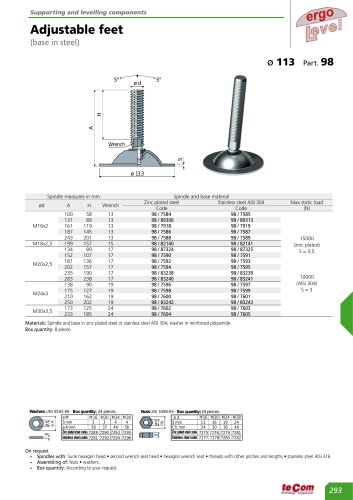 Adjustable feet
1 Page
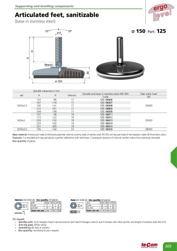
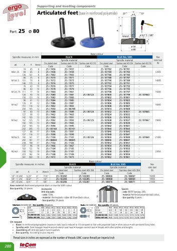 Articulated feet
1 Page
 PA articulated feet
1 Page
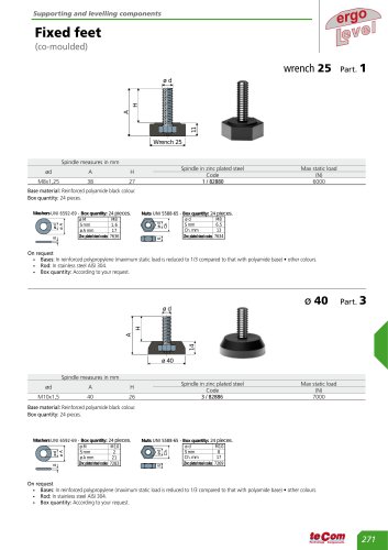 Fixed feet
1 Page
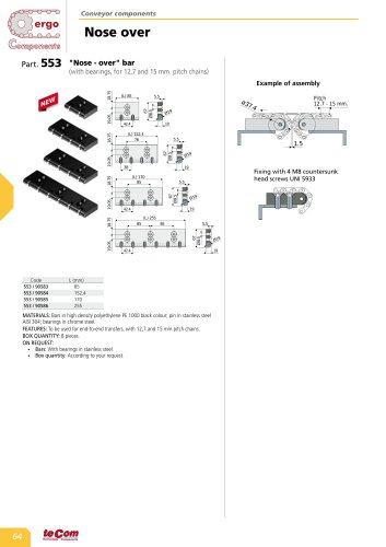 Nose over
1 Page
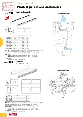 Label-saving guide
1 Page
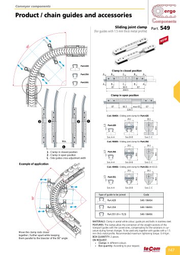 Sliding joint clamp
1 Page
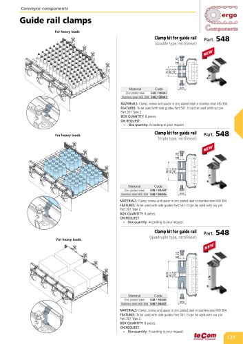 Clamp kit for guide rail
1 Page
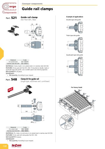 Guide rail clamps
1 Page
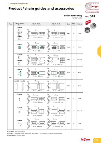 Rollers for bending
2 Pages
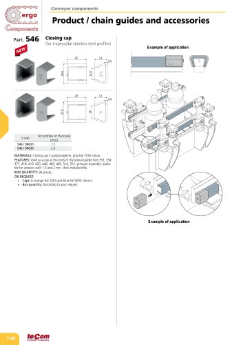 Closing cap
1 Page
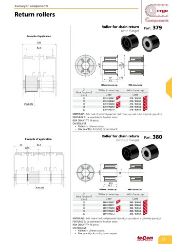 Roller for chain return
1 Page
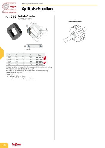 Split shaft collars
1 Page
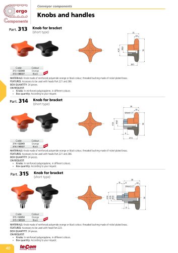 Knobs and handles
1 Page
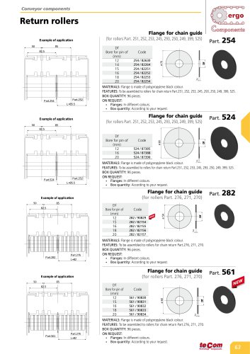 Return rollers
1 Page
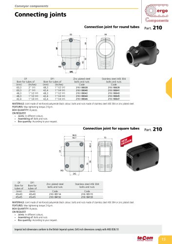 Connecting joints
1 Page
 CONVEYOR COMPONENT 2025
176 Pages
 SPECIAL PRODUCTS 2025
12 Pages
 GENERAL CATALOGUE 2025
348 Pages