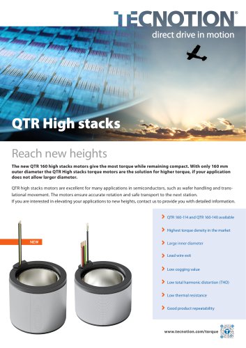
QTR 160 Torque motors
1 /2Pages
QTR 160 Torque motors
1 /2Pages
Catalog excerpts
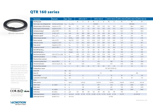
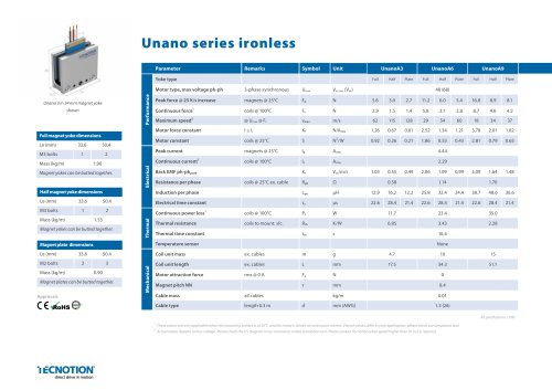
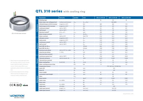
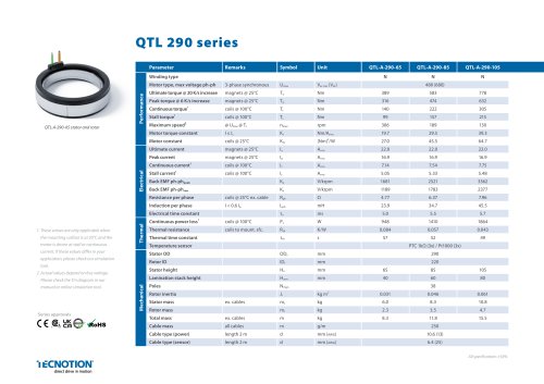
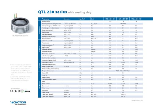
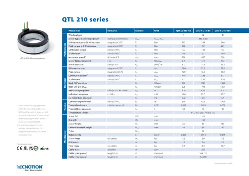
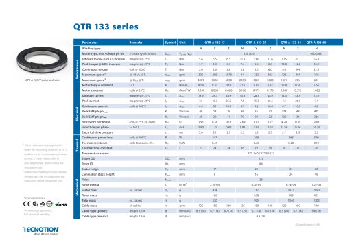
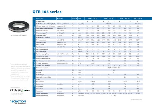
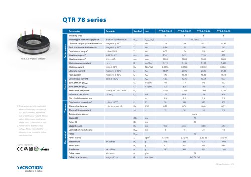
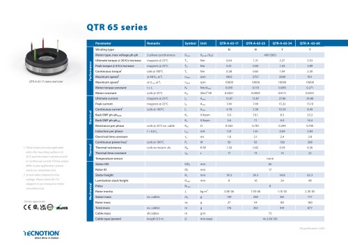
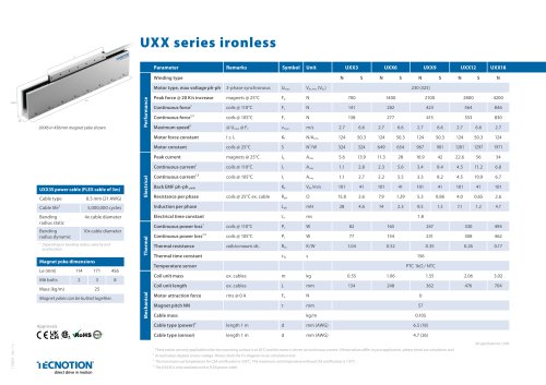
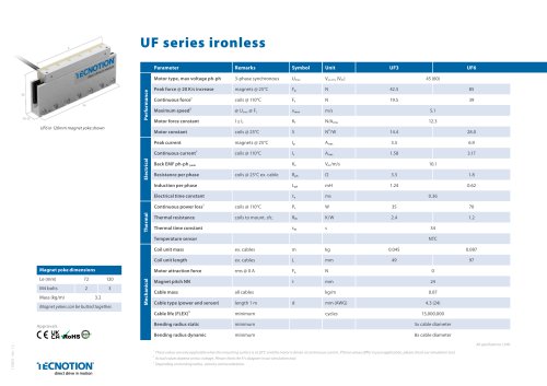
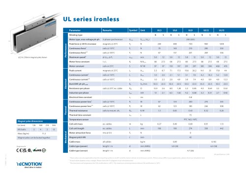
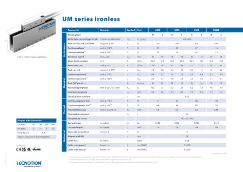
Winding type Motor type, max voltage ph-ph Ultimate torque @ 20 K/s increase Peak torque @ 6 K/s increase Continuous torque1 I Maximum speed2 Maximum speed2 I Motor torque constant Motor constant I Ultimate current Peak current 3-phase synchronous Umax Vac ,ms(Vdc) 1 These values are only applicable when the mounting surface is at 20°C and the motor is driven at continuous current. If these values differ in your application, please check our simulation tool. 2 Actual values depend on bus voltage. Please check the T/n diagram in our manual or online simulation tool. Series approvals *N-windings approved, full approval pending. Resistance per phase I Induction per phase Electrical time constant Continuous power loss1 Thermal resistance Thermal time constant Temperature sensor Stator OD Rotor ID I Stator height Lamination stack height Poles Rotor inertia I Stator mass Rotor mass I Total mass Cable mass I Cable type (power) Cable type (sensor) ex. cables all cables length 0.5 m length 0.5 m direct drive in motion
Open the catalog to page 1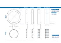
Mounting instructions and tolerances can be found in the torque installation manual. Manuals and 3D CAD files can be downloaded from our website.
Open the catalog to page 2All Tecnotion catalogs and technical brochures
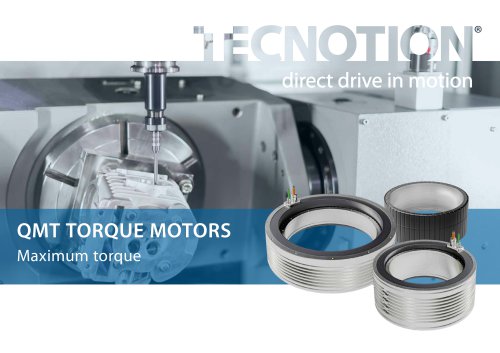 QMT Torque Motors
24 Pages
 Unano Ironless leaflet
2 Pages
 TD Iron core
2 Pages
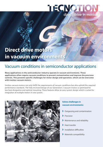
 Vacuum brochure English
16 Pages
 Unano Specsheet
2 Pages
 Ironless linear motor brochure
28 Pages
 Unano ironless applications
2 Pages
 Motor portfolio
2 Pages
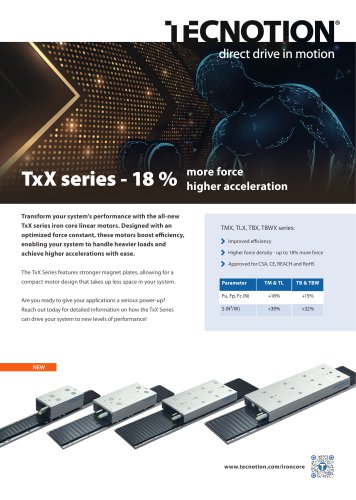 TxX ironcore leaflet
2 Pages
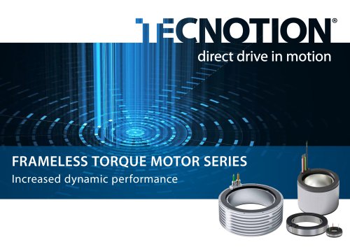 Frameless torque motor brochures
36 Pages
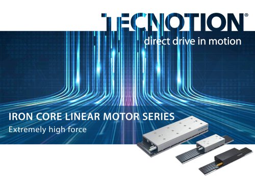 Iron core linear motor brochure
36 Pages
 Vacuum-UXXV G2 series
16 Pages
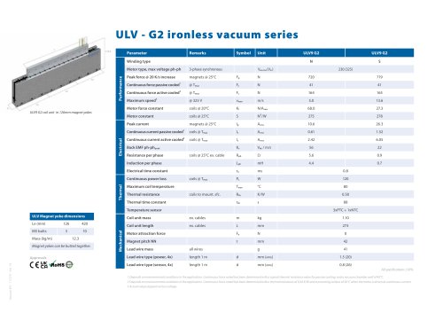 Vacuum-ULV G2 series
2 Pages
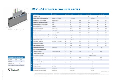 Vacuum-UMV G2 series
2 Pages
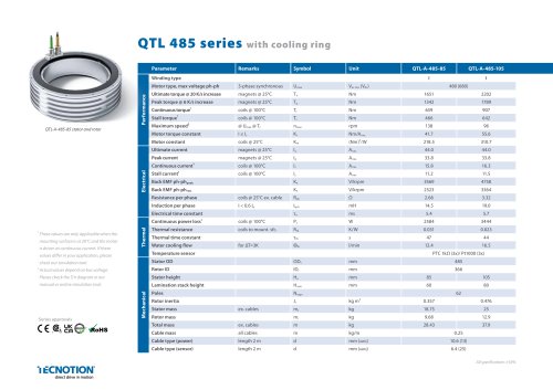 QTL 485 Torque motors
2 Pages
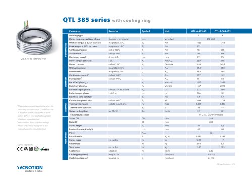 QTL 385 Torque motors
2 Pages
 QTL 310 Torque motors
2 Pages
 QTL 290 Torque motors
2 Pages
 QTL 230 Torque motors
2 Pages
 QTL 210 Torque motors
2 Pages
 QTR 133 Torque motors
2 Pages
 QTR 105 Torque motors
2 Pages
 QTR 78 Torque motors
2 Pages
 QTR 65 torque series
2 Pages
 UXX SERIES
2 Pages
 UXA SERIES
2 Pages
 UF SERIES
2 Pages
 UL SERIES
2 Pages
 UM SERIES
2 Pages
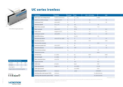 UC SERIES
2 Pages
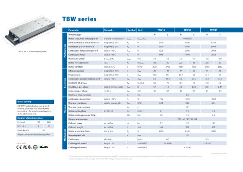 TBW serie
2 Pages
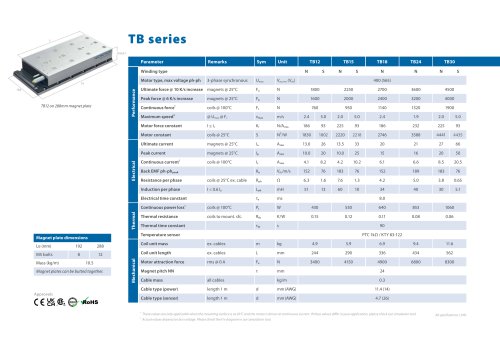 TB series
2 Pages
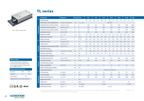 TL Series
2 Pages
 TM series
2 Pages
 TL48
TL482 Pages
 Simulation tool
2 Pages
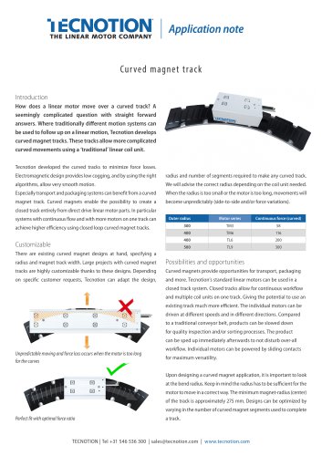 transport conveyer
2 Pages
- Liebherr electric motor
- Liebherr synchronous motor
- Alternating current motor
- Liebherr multipole motor
- Three-phase motor
- Liebherr position sensor
- Liebherr permanent magnet motor
- Liebherr linear position sensor
- Liebherr cable harness
- Custom motor
- Liebherr analog position sensor
- Liebherr robotic motor
- Liebherr non-contact position sensor
- Industrial position sensor
- Liebherr linear motor
- Liebherr packaging machine motor
- Liebherr machine tool motor
- Liebherr motor for medical applications
- Liebherr high-precision motor
- Liebherr torque motor