
Catalog excerpts
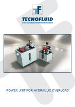
POWER UNIT FOR HYDRAULIC OVERLOAD
Open the catalog to page 1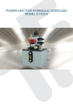
POWER UNIT FOR HYDRAULIC OVERLOAD MODEL 5-1520-0
Open the catalog to page 2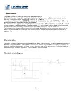
Requirements The system consists of a hydropneumatic power unit code 5-1520-*-0. Such device has been designed for supplying the hydraulic preloading pressure to the hydraulic overload valve for one-point suspension eccentric presses code 3-1517-*-0 and 3-1548-*-0. Hence the use of power unit code 5-1520-*-0 is dependent on the adoption of valve code 3-1517-*-0 or 3-1548-*-0 for whose characteristics, see relative technical documentation. The compressed air supply line connecting the press to power unit code 5-1520-*-0 should be equipped with a normally closed, 2-position, 3-way solenoid...
Open the catalog to page 3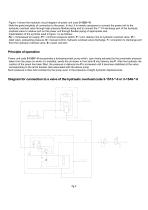
Figure 1 shows the hydraulic circuit diagram of power unit code 5-1520-*-0. Note the great simplicity of connection to the press. In fact, it is merely necessary to connect the power unit to the hydraulic overload valve through high pressure flexible piping and to connect the 1”1/4 discharge port of the hydraulic overload valve to relative port on the power unit through flexible piping of appropriate size. Interpretation of the symbols used in figure 1 is as follows: Pp = compressed air supply, Pr = minimum pressure switch, P = port, delivery line to hydraulic overload valve, Vt = relief...
Open the catalog to page 4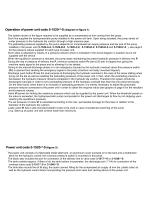
Operation of power unit code 5-1520-*-0 (diagram in figure 1) The system shown in the figure requires to be supplied by a compressed air line coming from the press. Such line supplies the hydropneumatic pump installed in the power unit tank. Upon being actuated, the pump sends oil under pressure to the hydraulic die cushion through a high pressure pipe. The preloading pressure supplied by the pump depends on compressed air supply pressure and the size of the pump installed in the power unit (5-1520-A-0, 5-1520-B-0, 5-1520-C-0, 5-1520-D-0, 5-1520-E-0 and 5-1520-F-0 ), see page 6 for the...
Open the catalog to page 5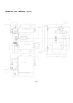
Power unit code 5-1520-*-0 ( figure 3)
Open the catalog to page 6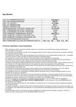
Specification AIR - OIL COMPRESSION RATIO MAX. PRELOADING PRESSURE MAX. OIL VISCOSITY MAX. OIL TEMPERATURE AMBIENT TEMPERATURE GUARANTEED MIN. FLOW RATE, POWER UNIT MIN. COMPRESSED AIR SUPPLY PRESSURE MAX. COMPRESSED AIR SUPPLY PRESSURE PORT DIAMETER, COMPRESSED AIR INLET PORT DIAMETER, HYDRAULIC DELIVERY LINE PORT DIAMETER, HYDRAULIC DISCHARGE LINE MAX. RETURN PRESSURE ON BLOCK MAX. PERMISSIBLE VOLTAGE ON PRESSURE SWITCH See page 5 380 bar 10° Engler 90° C. -10 +50 ° C. 1.5 L/minute 1.5 bar 7 bar PIPE DIA. 8 1/4” 1”1/4 500 bar 42 V. 4 A. AC 42 V. 2 A. Practical installation recommendations...
Open the catalog to page 7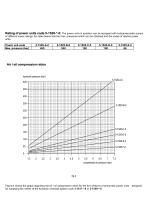
Rating of power units code 5-1520-*-0: The power units in question can be equipped with hydropneumatic pumps of different power ratings; the table below lists the max. pressures which can be obtained and the codes of relative power units. Power unit code Max. pressure (bar) Figure 4 shows the graph regarding the air / oil compression ratios for the five versions of pneumatic power units for supplying the valves of the hydraulic overload system code 3-1517-*-0 or 3-1548-*-0.
Open the catalog to page 8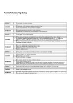
Possible failures during start-up The power unit does not start The power unit's pressure reducer is set to 0 bar The compressed air line is closed or clogged Screw the pressure reducer’s knob clockwise Check the compressed air line upstream of the power unit The power unit functions slowly 1 2 3 4 EFFECT CAUSE The pressure reducer connected to the power unit is calibrated at less than 1.5 bar A pressure reducer calibrated at less than 2 bar is positioned upstream of the power unit There's a choke on the line upstream of the power unit (e.g. bent or crushed pipe) The control unit has...
Open the catalog to page 9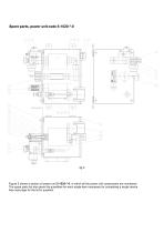
Spare parts, power unit code 5-1520-*-0 Figure 5 shows a section of power unit 5-1520-*-0, in which all the power unit components are numbered. The spare parts list also gives the quantities for each single item necessary for completing a single device. See next page for the list in question.
Open the catalog to page 10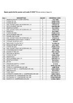
Spare parts list for power unit code 5-1520-*-0 (see section in figure 5) MANIFOLD BLOCK, CLAMP CONTROL O-RING OR 106 O-RING OR 3037 HEX. SOCKET HEAD CAP SCREW M6 x 10 METAL/RUBBER RING M6 MANIFOLD SCREW HEX. SOCKET HEAD CAP SCREW M5 x 35 MANIFOLD O-RING OR 2056 METAL/RUBBER RING 3/8”. POWER UNIT COVER HEX. SOCKET HEAD CAP SCREW M6 x 12 COMPRESSED AIR FITTING ¼” HOSE 8 DYNAMIC SILENCER 3/8”G. BREATHER / FILLER CAP ¾” MODULAR RELIEF VALVE O-RING OR 2025 HEX. SOCKET HEAD CAP SCREW M6 x 30 HYDROPNEUMATIC PUMP ELBOW FITTING 3/8”. SUCTION FILTER 90 µ O-RING OR 2087 DRAIN PLUG METAL/RUBBER RING...
Open the catalog to page 11
N.B. WHEN ORDERING SPARE PARTS, ALWAYS STATE THE SERIAL NUMBER STAMPED ON THE NAMEPLATE AFFIXED TO THE POWER UNIT COVER FOR ALL THOSE PARTS WHOSE CODE IS GIVEN BETWEEN BRACKETS IN THE LIST APPEARING ON PAGE 9. THE HYDROPNEUMATIC UNITS DESCRIBED IN THIS MANUAL HAVE BEEN DESIGNED AND MANUFACTURED ACCORDING TO CRITERIA AIMED AT PREVENTING INJURY TO PERSONS OR DAMAGE TO OBJECTS; HOWEVER IT SHOULD BE POINTED OUT THAT, AS THE HYDROPNEUMATIC POWER UNITS ARE PRESSURE GENERATORS, THE IMPROPER USE OF SUCH DEVICE COULD BE POTENTIALLY HAZARDOUS.
Open the catalog to page 12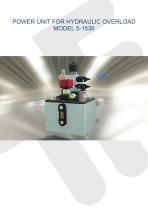
POWER UNIT FOR HYDRAULIC OVERLOAD MODEL 5-1536
Open the catalog to page 13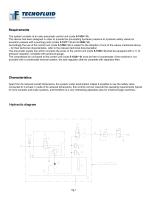
Requirements The system consists of an oleo-pneumatic control unit (code 5-1536-*-0). This device has been designed in order to provide the pre-loading hydraulic pressure to hydraulic safety valves for eccentric presses with a pushing point (codes 3-1517-*-0 and 3-1548-*-0). Accordingly the use of the control unit (code 5-1536-*-0) is subject to the adoption of one of the valves mentioned above – for their technical characteristics, refer to the relevant technical documentation The pneumatic supply line which connects the press to the control unit (code 5-1536-*-0) shall be equipped with a...
Open the catalog to page 14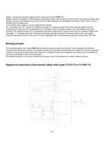
Figure 1 shows the hydraulic diagram of the control unit (code 5-1536-*-0). Please note that connection to the machine is extremely simple: just connect the control unit to the hydraulic safety valve directly, through a HP flexible hose, and connect its outlet opening to the dedicated connection of the control unit, by a flexible hose of suitable size. The symbols used in figure 1 can be interpreted as follows: A = pneumatic feed P = control unit’s delivery coupling T= outlet connection (from the hydraulic safety valve) 1= compressed air lubricator 2= compressed ait cut-off electrovalve 3=...
Open the catalog to page 15All Tecnofluid Engineering SrL catalogs and technical brochures
-
HYDRAULIC SPEED GOVERNORS
4 Pages
-
HYDRAULIC LOCK CYLINDERS
11 Pages
-
COMPACT HYDRAULIC CYLINDERS
17 Pages
-
OLEO PNEUMATIC PUMPS
12 Pages
-
HYDRAULIC SPEED GOVERNOR
12 Pages
-
HYDROPNEUMATIC CYLINDER
8 Pages
-
LOCKING HYDRAULIC POWER UNITS
11 Pages
-
OVERLOAD SAFETY VALVES
25 Pages
-
HYDRAULIC LOCK CYLINDERS
11 Pages
-
SHORT-STROKE CYLINDERS
8 Pages
-
Shock absorber stroke 15mm
12 Pages


