- Catalogs
- TechNexion Ltd.
- PIXI-9377

PIXI-9377
PIXI-9377
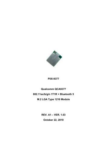
The PIXI-9377 is a high-performance WLAN and Bluetooth combo module based on the Qualcomm Atheros QCA9377 chipset. It supports dual-band frequencies (2.4GHz and 5GHz) and is designed for industrial applications with a wide temperature range and multiple certifications. The module features an on-module chip antenna and supports Linux and Android drivers, simplifying integration.
Product Key Features
The module is available in an M.2 LGA Type 1216 form factor, operating between -40 to +85 degrees Celsius. It supports Wi-Fi standards 802.11a/b/g/n/ac with a 1T1R radio stream and Bluetooth 5 with backward compatibility.
Product Variants
Two main configurations are available: PIXI-9377-S (Wi-Fi via SDIO, Bluetooth via UART + PCM) and PIXI-9377-P (Wi-Fi via PCIe, Bluetooth via USB).
Add-On Card Variants
TechNexion offers several add-on cards for easier integration, including CLIX-9377, STIX-M2-9377-AE, STIX-M2-9377-B, and STIX-MPCIE-9377, each with different interface options.
Signal Pinout
The document provides a detailed pinout for the PIXI-9377, covering power, ground, and various signal connections for both Wi-Fi and Bluetooth functionalities.
RF Characteristics
The module's RF characteristics include RX sensitivity and TX output power for both 2.4 GHz and 5 GHz bands, along with Bluetooth specifications.
Power Consumption
Tables detail the power consumption for different Wi-Fi and Bluetooth modes, highlighting the module's efficiency under various conditions.
Compliance and Integration
Guidelines for EMC compliance, antenna integration, and reference schematics for integrating the module into different designs are included.
Packaging and Ordering Information
Information on packaging, labeling, and ordering is provided to assist in procurement and logistics.
The PIXI-9377 module operates at 3.3V and 1.8V, with specific parameters for each voltage mode. TX output power for 5 GHz Wi-Fi varies by protocol, with current consumption ranging from 430 mA to 510 mA. Bluetooth power consumption is detailed for various modes, with continuous RX burst at 22 mA and TX Class 2 at 39 mA to 66 mA.
Electric Specifications
The module supports both 3.3V and 1.8V operation modes, with specific voltage ranges for VDD_3P3, VDD_IO, and VDD_SDIO. Power domain pins are specified for connection.
Power Sequence Specifications
Detailed power sequence requirements are provided for both 3.3V and 1.8V operation modes, including timing parameters for power rail connections and signal assertions.
Reference Schematics
Schematics for PIXI-9377-S (SDIO) and PIXI-9377-P (PCIe) are provided, along with integration considerations to avoid common design mistakes.
EMC Compliance Certification
The module is certified as a Modular Radio under various standards, allowing integration without recertification. End-product testing requirements for FCC compliance are outlined, including permissive change options for product modifications.
Antenna Integration Guidelines
Recommendations for antenna placement and integration are provided to ensure optimal performance and compliance with separation distance requirements.
The PIXI-9377 module includes an on-board IPEX MHF4 antenna connector. Specific dimensional criteria must be followed when selecting a mating coax patch cable.
Certified Antenna Options
The module is FCC/IC/TELEC certified with approved antennas, including:
- ANTP150P232525D2450MHF4: Internal patch antenna (1.5dB)
- ANTP180A138045D2450MHF4: External Dipole antenna (2dB)
- ANTP180A207070D2450MHF4: External Dipole antenna (7dB)
SMT and Layout Data
Data is available in native file format upon request from TechNexion sales.
Packaging Information
Modules are packaged in trays or reels, with a full reel containing 1000 modules. Specific dimensions and tolerances are provided.
Labelling Information
Each module contains a unique serial label.
Ordering Information
Available configurations include:
- PIXI-9377-S: QCA9377 SDIO 802.11ac + UART BT 5 MODULE
- PIXI-9377-P: QCA9377 PCIE 802.11ac + USB BT 5 MODULE
Important Notice
TechNexion reserves the right to make changes to products and services without notice. Products are sold subject to TechNexion's terms and conditions. The company does not assume liability for applications assistance or customer product design. Products are not authorized for use in safety-critical, military/aerospace, or automotive applications unless specifically designated.
Disclaimer
TechNexion Ltd. reserves the right to change details in this publication without notice. No warranty of accuracy is given, and no liability is accepted for omissions or inaccuracies.
Catalog excerpts
Qualcomm QCA9377 802.11ac/b/g/n 1T1R + Bluetooth 5 M.2 LGA Type 1216 Module
Open the catalog to page 1
1. Introduction 1.1 General Introduction PIXI-9377 is a high performance 2.4 + 5GHz WLAN and Bluetooth combo module based on latestgeneration silicon (Qualcomm Atheros QCA9377). With an industrial temperature rating, broad country certifications, and the availability in different package styles, the PIXI-9377 provides significant flexibility to meet various end user application needs. The on-module chip antenna package style for the PIXI-9377 eliminates complexity for design integration, simplifies manufacturing assembly with larger pin outs, and features an advanced chip antenna that offers...
Open the catalog to page 4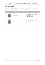
PIXI-9377 REV. A1. HARDWARE MANUAL – VER 1.02 – OCT 22 2019 1.3 Product Variants The PIXI-9377 Base Module is a System in Package (SIP) module, which can be assembled into an OEM end product and is available in the following configurations. Description PIXI QCA9377 M.2 SIP Module Wi-Fi : SDIO BT : UART + PCM
Open the catalog to page 6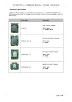
PIXI-9377 REV. A1. HARDWARE MANUAL – VER 1.02 – OCT 22 2019 1.4 Add-On Card Variants TechNexion offers a range of “add-on cards” for customers that want to add the PIXI-9377 in their OEM project but don’t have the freedom or technical design or manufacturing knowledge to work with SIP packages Wi-Fi : SDIO BT : UART + PCM
Open the catalog to page 7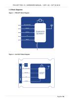
PIXI-9377 REV. A1. HARDWARE MANUAL – VER 1.02 – OCT 22 2019 1.5 Block Diagrams Figure 1 – PIXI-9377 Block Diagram Figure 2 – CLIX-9377 Block Diagram
Open the catalog to page 8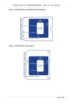
PIXI-9377 REV. A1. HARDWARE MANUAL – VER 1.02 – OCT 22 2019 Figure 3 – STIX-M2-9377AE and STIX-M2-9377B Block Diagram Figure 4 – STIX-MPCIE-9377 Block Diagram
Open the catalog to page 9
PIXI-9377 REV. A1. HARDWARE MANUAL – VER 1.02 – OCT 22 2019 1.6 Dimensional Drawing PIXI-9377 Figure 5 – PIXI-9377 Dimensional Drawing
Open the catalog to page 10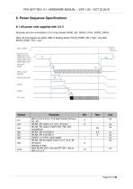
6.1 All power rails supplied with 3.3 V All power pins are connected to 3.3 V only include VDDIO_AO, VDDIO_XTAL, VDDIO_GPIOx. Note: All host signals are either GND or floating before WLAN_EN/BT_EN - ’high”, and after WLAN EN/BT EN = Low.
Open the catalog to page 17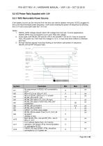
If the battery source can be removed from the end user device (battery removed, AC/DC plugged in), this is the recommended power sequence. It will avoid violating the power off sequence by allowing the 3.3 V rail to shut down after the 1.8 V rail. 1. VDDIO_GPIO voltage should match VIO voltage from the host. In some applications, VDDIO_GPIO may connected to 3.3 V upon Host VIO voltage. 2. In this case, both WLAN_EN and BT_EN on the QCA9377 are at 3.3 V due to using the VDD_AO power rail. If the host VIO voltage is 1.8 V, it must have level shifters to interface with host. 3. All host interface...
Open the catalog to page 18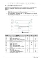
6.2.2. Without Removable Power Source If the battery source cannot be removed from the end user device, this is the recommended power sequence for this application. This sequence allows the software to control the power on/off sequence. Notes: 1. VDDIO_GPIO voltage should match VIO voltage from the host. In some applications, VDDIO_GPIO may connected to 3.3 V upon host VIO voltage. 2. Both WLAN_EN and BT_EN of QCA9377 are 1.8 V. If host VIO voltage is 1.8 V, it does not need level shifter to interface with host. 3. All host interface signals must stay floating or low before WLAN_EN/BT_EN - ’high”,...
Open the catalog to page 19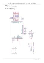
7 Reference Schematics 7.1 PIXI-9377-S (SDIO)
Open the catalog to page 20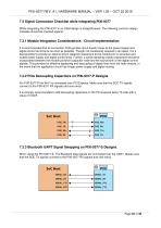
PIXI-9377 REV. A1. HARDWARE MANUAL – VER 1.02 – OCT 22 2019 7.3 Signal Connection Checklist while integrating PIXI-9377 While integrating the PIXI-9377 in an OEM design is straightforward. The following common design mistakes should be checked against. 7.3.1 Module Integration Considerations - Circuit Implementation It is recommended that all connection PCB (printed circuit board) traces to the power supply and digital control terminal be as short as possible. Though not necessarily required in all cases, it is a best practice to provide an optional shunt capacitor placement at the module pin...
Open the catalog to page 22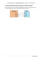
PIXI-9377 REV. A1. HARDWARE MANUAL – VER 1.02 – OCT 22 2019 7.3.4 Bluetooth PCM Audio Signal Swapping on PIXI-9377-S Designs. When using the PIXI-9277-S. The Bluetooth audio signals are connected over the PCM. Makes sure that the SOC IN signals connect to the PIXI-9377 OUT signal and vice-versa.
Open the catalog to page 23
8. EMC Compliance certification The PIXI-9377 module has been tested and approved as a Modular Radio in accordance with the appropriate FCC, IC, ETSI, RED, TELEC and RCM standards. The supporting test data modular test report can be found on our corporate homepage download section at www.technexion.com. Since this module and its associated set of approved antennas have been certified as a Modular Radio, this allows the end user to integrate this module into an end-product without the requirement of recertifying the radio module. The module-integrator is responsible for the unintentional conducted...
Open the catalog to page 24
PIXI-9377 REV. A1. HARDWARE MANUAL – VER 1.02 – OCT 22 2019 8.2 FCC Wireless certification: New Filing vs. Permissive Change Products are continually under revision due to obsolete or unavailable parts, cost cutting, updates for a product release, and so on. The dilemma for most companies is determining the process and requirements for altered products. This section outlines the options available and highlights a few examples for guidance. Here we focus on changes for unlicensed transmitters that require an FCC Certification or Equipment Authorization. Products require “Document of Compliance”...
Open the catalog to page 25
PIXI-9377 REV. A1. HARDWARE MANUAL – VER 1.02 – OCT 22 2019 specification sheet for cutoff frequencies).[FCC source: 178919 D01 Permissive Change Policy v04r04] Therefore, if the antenna is of a different type or higher gain, the product or radio module requires a Class II Permissive Change, and all FCC provisions of Title 47 CFR 15.203 for antenna requirements must be met. Example 2: Electrical Hardware Changes The main deciding factor for hardware changes is whether the device is “electrically equivalent.” If the device is electrically equivalent, a Class I or Class II Permissive Change is...
Open the catalog to page 26All TechNexion Ltd. catalogs and technical brochures
 PICO-IMX7
2 Pages
 EDM-GNOME-IMX7
2 Pages
 TWP-1560-IMX6
3 Pages
 PICO-IMX8M-MINI
2 Pages
 PICO-IMX8M
2 Pages
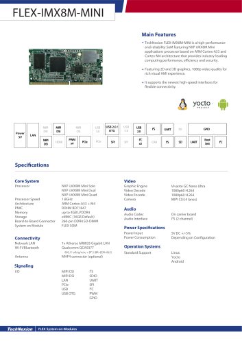 FLEX-IMX8M-MINI
2 Pages
 EDM Series System on Modules
8 Pages
 TEK Series Box PC
8 Pages
 TEP Series Modules HMI
8 Pages