- Products
- Catalogs
- News & Trends
- Exhibitions
DRB1
1 /22Pages

DRB1
1 /22Pages
Catalog excerpts
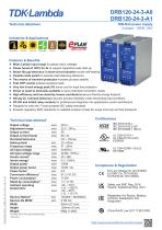
DIN-Rail power supply 3 phase / 120W / 24V Technical datasheet Industries & Applications Features & Benefits ► Wide 3 phase input range for global mains voltages ► Power boost of 120% for 2s to support capacitive loads start-up ► Smart Hiccup behaviour in short-circuit situation avoids self-heating ► Parallel mode switch to activate load balancing behaviour ► Two means of transient protection increase process stability ► Fast OVP control protects sensitive loads ► Very low inrush energy peak (I²t) saves cost for input line protection ► Screw or push-in terminals available to serve individual connection needs ► High efficiency and low stand-by losses contribute to an eco-friendly energy footprint ► Strong CC overload behaviour secures process reliability under demanding load conditions ► DC-OK and inhibit relay contacts for professional integration into applications control architecture ► Designed to meet the 7 most accepted IEC safety standards ► Exceeds regulatory EMC standards on radiated emission (Class B), surge immunity and fast transients Technical data abstract1 Output voltage Adjustment range Output current Output current boost Overload behaviour Hold-up time2 Frequency range AC Input voltage AC Input voltage range Inrush current2 Inrush energy2 Output power Output power boost Power factor2 Conversion efficiency2 Power consumption Stand-by consumption2 Ambient operating temperature Service lifetime2 Service life MTBF Width Height Weight 1 Compliance & Registration EU Low Voltage Dir. 2014/35/EU EU EMC Dir. 2014/30/EU EU RoHS Dir. 2011/65/EU Safety and EMC Reg. 2016 Hazard. Substances Reg. 2012 Registration for Russia, Belarus, Armenia, Kazakhstan and Kyrgyzstan 10 All values refer to STC unless otherwise stated
Open the catalog to page 1
Commercial information Order codes HS code Life-cycle status Single packaging dimensions Width Height Depth Gross weight Multiple packaging quantity Manufacturer warranty Model selector Model name Output Power Output Voltage Screw terminals Push-in terminals Screw terminals Push-in terminals Screw terminals Push-in terminals Screw terminals Push-in terminals 20A buffer module for short-term hold-up or peak power in 24VDC load systems. 40A redundancy module for creating redundant power supply systems up to 2x 20A. 40A redundancy module with additional signaling features for creating redundant...
Open the catalog to page 2
List of abbreviations avg. CC chap. Dir. eCap EMC Iac Iout Iout_boost Iout_nom Iout_ol Iout_sc ITU max. OCP OTP OVP PELV Pout Pout_boost Pout_nom PSU Reg. SELV STC typ. Uout Uout_nom Uset UVP Vac Vac_nom / .. The arithmetic average calculated from a row of values. Constant output current Chapter Directive Electrolytic capacitor Electromagnetic Compatibility AC input current under a particular operating condition DC output current under a particular operating condition Max. DC output current (time limited) without a shortfall of Uset. Nominal DC output current Max. intermittent DC output current...
Open the catalog to page 4
1. General 1.1 Handling of the product To ensure faultless and safe operation of the products it is required to observe the specified ambient conditions for transport and storage (see "Ambient conditions" on page 9), set-up, assembly, installation, commissioning, operation and maintenance. 1.2 Protection enclosure required The device must be installed in a protective housing or control cabinet to which only qualified personnel have access. 1.3 Humid environments Do not operate the device in a damp environment or in an environment where condensation is likely to occur. 1.4 Switch/Circuit-breaker...
Open the catalog to page 5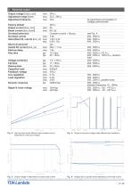
2. Electrical output Output voltage [Uout_nom] Adjustment range [Uset] Adjustment tolerance Factory default Output current [Iout_nom] Boost current [Iout_boost] Overload behaviour Overload current Intermittent OL current [Iout_ol] at upper/lower end position of voltage potentiometer Short-circuit proof Instant SC current [Iout_sc] Start-up delay Rise time Voltage overshoot Fall time Hold-up time Capacitive load Feedback voltage Line regulation Load regulation Dynamic response Ripple & noise voltage Fig. 3: Hold-up times under different load conditions and in dependence of the input voltage Normal...
Open the catalog to page 6
3. Electrical input AC power systems Mains Frequency Frequency range AC input voltage [Vac_nom] Voltage range Turn-ON voltage Turn-OFF voltage AC input current AC input current RMS Crest factor Inrush current Inrush energy Input capacitance Input mains voltage Fig. 7: Inrush current and energy during start-up phase Unless otherwise stated, all values are specified in normal mounting position, at full load, nominal input and output voltages, 25°C (77°F) ambient temperature and a run-in time of
Open the catalog to page 7
4. Performance Output power [Pout_nom] Boost power [Pout_boost] Dropped phase power Apparent input power Active input power Reactive input power Power factor Conversion efficiency Power consumption Stand-by consumption CONVERSION EFFICIENCY [%] Fig. 8: Conversion efficiency in dependence of the output power Fig. 9: Power losses in dependence of the output power 0,6 Pout_nom Cycle duration (CD) Fig. 10: Cycle duration in dependence of the ambient temperature and usage of the full boost power (120% / 2s) Fig. 11: Input power factor in dependence of the output current TYP. INPUT CURRENT PER PHASE...
Open the catalog to page 8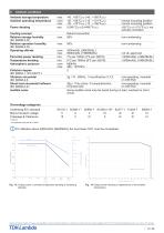
5. Ambient conditions Ambient storage temperature Ambient operating temperature Pollution degree IEC 60664-1, IEC 62477-1 Vibration sinusoidal IEC 60068-2-6 Shock test sinosoidal halfwave IEC 60068-2-27 Audible noise Percental power derating Temperature derating Atmospheric pressure Cooling concept Relative storage humidity IEC 60068-2-30 Relative operation humidity IEC 60068-2-30 Operating altitude Power derating normal mounting position normal mounting position >55°Camb (>131°Famb), not actively controlled non-condensing non-condensing not UL approved >3000mASL (>9842ftASL) >3000mASL (>9842ftASL)...
Open the catalog to page 9
6. Reliability and Service lifetime Service lifetime min. Early life MTBF Telcordia SR-332 Issue 4 Service life MTBF Telcordia SR-332 Issue 4 he maximum service lifetime guaranteed by the eCap manufacturer is 131 400hrs (15 years). All values above T are theoretically calculated. 800 3 LIFE CYCLE PHASE Fig. 15: Power supply service lifetime in dependence of ambient temperature Service life (model dependent) Fig. 16: Generic diagram visualising failure rate and MTBF values during the products life-cycle Unless otherwise stated, all values are specified in normal mounting position, at full load,...
Open the catalog to page 10All TDK-Lambda catalogs and technical brochures
 DBM20
DBM206 Pages
 CUS600M
12 Pages
 cus500m1
9 Pages
 CUS400M-
11 Pages
 CUS350MPE
5 Pages
 CHVM
CHVM5 Pages
 Programmable Power Supplies
71 Pages
 Programmable Power Supplies
16 Pages
 AC-DC Power Supplies
257 Pages
 DC-DC Power Supplies
158 Pages
 Configurable Power Supplies
60 Pages


- DC power supply
- AC/DC power supply
- CE power supply
- Single-output power supply
- Switching power supply
- Power supply for industrial applications
- DC-DC converter
- Tabletop power supply
- Compact power supply
- Electronic filter
- DIN rail power supply
- Variable-output power supply
- Rack-mount power supply
- Single-phase power supply
- Passive electronic filter
- Programmable power supply
- Laboratory power supply
- Regulated power supply
- Telecommunications equipment power supply