- Catalogs
- TDK Electronics Europe
- Pin Terminal Type PFC
Pin Terminal Type PFC
1 /14Pages

Pin Terminal Type PFC
1 /14Pages
Catalog excerpts

Choke Coils for PFC Pin terminal type PFC(QM) series PFC(ER) series Type: Issue date: • All specifications are subject to change without notice. • Conformity to RoHS Directive: This means that, in conformity with EU Directive 2002/95/EC, lead, cadmium, mercury, hexavalent chromium, and specific bromine-based flame retardants, PBB and PBDE, have not been used, except for exempted applications.
Open the catalog to page 1
Choke Coils for PFC PFC Series Contents • All specifications are subject to change without notice.
Open the catalog to page 2
Choke Coils for PFC PFC Series Conformity to RoHS Directive Development Concept This small and thin PFC choke coil utilizes a power factor-improving circuit, which is suitable for the smaller and thinner electronic devices of recent years. MATERIAL Thanks to the development of an optimized core shape and materials, the choke coil has DC superimposition characteristics suitable for the design of various types of electronic devices. Optimized materials have been selected, and at the same time a small and thin PFC core with TDK's proprietary core shape has been developed. The product line-up has...
Open the catalog to page 3
• Large current is achieved in a small shape. AV equipment, digital consumer electronics PRODUCT IDENTIFICATION (5) Rated peek current code : Standard product [ ] : Customized product [ ) : Dropped substrate Mount method The rated peak current is determined by the peak value of the triangular waveform current when the temperature increase is less than 40°C during continuous operation. • All specifications are subject to change without notice.
Open the catalog to page 4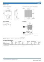
CIRCUIT DIAGRAM RECOMMENDED BASE MATERIAL OPENING SIZE ELECTRICAL CHARACTERISTICS Part No. PFC3811QM-221K05B-00 ∗1 ∗2 Input voltage Eac(V) 85 to 264 Peak current at OCP OCP Saturation margin current∗2(A) 120% 5.5 Turn ratio (Np/Npd) 10.3 The rated peak current is determined by the peak value of the triangular waveform current when the temperature increase is less than 40°C during continuous operation. The saturated current is specified as a current whose inductance decreases by 20% at a constant temperature of 100°C. • All specifications are subject to change without notice. 003-03 / 20100927...
Open the catalog to page 5
RECOMMENDED BASE MATERIAL OPENING SIZE 6 ELECTRICAL CHARACTERISTICS Part No. PFC3812QM-221K06B-00R ∗1 ∗2 Input voltage Eac(V) 85 to 264 Peak current at OCP OCP Saturation margin current∗2(A) 120% 8.3 Turn ratio (Np/Npd) 10.3 The rated peak current is determined by the peak value of the triangular waveform current when the temperature increase is less than 40°C during continuous operation. The saturated current is specified as a current whose inductance decreases by 20% at a constant temperature of 100°C. • All specifications are subject to change without notice. 003-03 / 20100927 / e633_pfc.fm...
Open the catalog to page 6
Input voltage Eac(V) 85 to 264 85 to 264 85 to 264 Peak current at OCP OCP Saturation margin current∗2(A) 120% 4.4 120% 6.0 120% 7.2 Turn ratio (Np/Npd) 10 9.8 9.6 The rated peak current is determined by the peak value of the triangular waveform current when the temperature increase is less than 40°C during continuous operation. The saturated current is specified as a current whose inductance decreases by 20% at a constant temperature of 100°C. • All specifications are subject to change without notice. 003-03 / 20100927 / e633_pfc.fm
Open the catalog to page 7
The rated peak current is determined by the peak value of the triangular waveform current when the temperature increase is less than 40°C during continuous operation. The saturated current is specified as a current whose inductance decreases by 20% at a constant temperature of 100°C. • All specifications are subject to change without notice. 003-03 / 20100927 / e633_pfc.fm
Open the catalog to page 8
ELECTRICAL CHARACTERISTICS Part No. PFC2723ER-601K02B-00 PFC2723ER-421K03B-00 ∗1 ∗2 Input voltage Eac(V) 85 to 264 85 to 264 Peak current at OCP OCP Saturation margin current∗2(A) 120% 3.3 120% 4.5 Turn ratio (Np/Npd) 9.8 10.8 The rated peak current is determined by the peak value of the triangular waveform current when the temperature increase is less than 40°C during continuous operation. The saturated current is specified as a current whose inductance decreases by 20% at a constant temperature of 100°C. • All specifications are subject to change without notice. 003-03 / 20100927 / e633_pfc.fm...
Open the catalog to page 9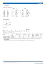
Input voltage Eac(V) 85 to 264 85 to 264 85 to 264 Peak current at OCP OCP Saturation margin current∗2(A) 150% 5.4 120% 7.0 120% 9.1 Turn ratio (Np/Npd) 10.0 10.4 9.0 The rated peak current is determined by the peak value of the triangular waveform current when the temperature increase is less than 40°C during continuous operation. The saturated current is specified as a current whose inductance decreases by 20% at a constant temperature of 100°C. • All specifications are subject to change without notice. 003-03 / 20100927 / e633_pfc.fm
Open the catalog to page 10
Input voltage Eac(V) 85 to 264 85 to 264 85 to 264 Peak current at OCP OCP Saturation margin current∗2(A) 150% 8.2 150% 11.1 120% 13.0 Turn ratio (Np/Npd) 10.4 10.0 10.5 The rated peak current is determined by the peak value of the triangular waveform current when the temperature increase is less than 40°C during continuous operation. The saturated current is specified as a current whose inductance decreases by 20% at a constant temperature of 100°C. • All specifications are subject to change without notice. 003-03 / 20100927 / e633_pfc.fm
Open the catalog to page 11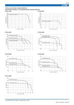
TYPICAL ELECTRICAL CHARACTERISTICS INDUCTANCE CHANGE vs. DC SUPERPOSITION CHARACTERISTICS PFC3811QM PFC3812QM • All specifications are subject to change without notice. 003-03 / 20100927 / e633_pfc.fm
Open the catalog to page 12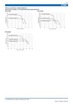
TYPICAL ELECTRICAL CHARACTERISTICS INDUCTANCE CHANGE vs. DC SUPERPOSITION CHARACTERISTICS • All specifications are subject to change without notice.
Open the catalog to page 13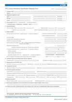
PFC Circuit Inductance Specification Request Form 2. Department, applicant's name Person in Charge from Sales Promotion Dep.: Person in Charge from Sales Dep.: _ Recorded Date Recorded Date / / Recorded Date / / 3. Circuit system (Fill in the (□) square like this (■) to make your selection.) □Continuous mode □Critical mode □Interleave neither ( ) AC input voltage: Rated _ (V) to _(V) Operating range: Frequency_ (Hz) Minimum operating input voltage: (1) Clock frequency (Fill in the (□) square like this (■) to make your selection.) (3) Rated output power/Maximum peak power (4) Minimum operating...
Open the catalog to page 14All TDK Electronics Europe catalogs and technical brochures
 YFF-HC series
5 Pages
 Aluminum electrolytic capacitors
18 Pages
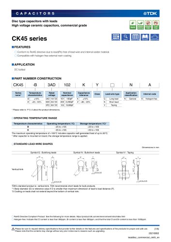 CK45 series
6 Pages

Archived catalogs
 SATA SSD
3 Pages
 CF CARD
3 Pages
 TDK MLCC CATALOG b11
72 Pages
 Wound Type SMD Inductors (Coils)
12 Pages
 Ferrite Magnets FB
27 Pages
 E Series
45 Pages
 Feed-back Type EFS
4 Pages
 Piezoelectric Type LTS, TSP
9 Pages
 Chip Beads STD
29 Pages
 Humidity Sensor CHS Series
11 Pages
 Color Video Camera
2 Pages
 Multilayer Chip Beads
27 Pages
 NTC Thermistors SMD
14 Pages
 Multilayer/Q-up MLG0402Q
5 Pages
 SMD NTCG
14 Pages
 Piezoelectric Receiver RU
2 Pages
 EFE300M / EFE400M 300/400
4 Pages
 PTC Thermistors
28 Pages
 Flip Chip Bonder
1 Page
 EMC and RF testing
4 Pages
 RF Integrated Test Systems
12 Pages
 Microwave Absorbers
16 Pages
 Power supplies catalog
24 Pages
 Planar Cores
8 Pages
 Toroidal Cores
2 Pages
 Ferrite Electrodes
4 Pages


![[BHF/BHP] Series for Barcode Printers, and Label Printers](https://img.directindustry.com/pdf/repository_di/34778/bhf-bhp-series-barcode-printers-label-printers-374455_1mg.jpg)


- Temperature probe
- Transformer
- Test cabinet
- Dry transformer
- Surge protector
- Resistance temperature sensor
- Level probe
- Liquid level sensor
- Capacitor
- Current transformer
- Position transducer
- Waterproof temperature sensor
- Power transformer
- Electronic filter
- Current sensor
- Industrial transformer
- Isolation transformer
- Passive electronic filter
- No-contact position sensor
- Solid-state drive