- Catalogs
- TDK Electronics Europe
- Organic Light Emitting Displays UEL162
Organic Light Emitting Displays UEL162
1 /1Page

Organic Light Emitting Displays UEL162
1 /1Page
Catalog excerpts

(1/1) 002-01 / 20080903 / el_el_uel162.fm • All specifications are subject to change without notice. Organic Light Emitting Display Area-color Type/Passive Matrix Method UEL Series UEL162 SHAPES AND DIMENSIONS SPECIFICATIONS PACKAGING STYLE AND QUANTITIES • To be separately arranged. PRECAUTIONS • The performance of this product is defined under particular conditions, and cannot be guaranteed under conditions of actual use. • This product is not to be applied for uses in which the absolute highest reliability is required due to the possibility of serious human injury or physical damage. For those cases, please contact us in advance. • If Foreign Exchange and Foreign Trade Law are applicable to this product (including service) requiring it to be regulated, export admission is needed under law. • The information in this document is provided as an example only, and cannot be guaranteed as the final design for mass production. • Please contact us for detailed information on the shape of the FPC part. PIN ASSIGNMENT Conformity to RoHS Directive 9.15 67.2 119dots(White) 1dots(Blank) 36dots(Blue) 85.5 15.5 3.25 25.2 5 14 23.8 19.5 0.3 29.2 20.5 22 34.9 3.3 78.9 40pin 1pin Active area Polaizer Protection resin Printing position of Lot.No. - Dimensions in mm 2.2 Protection resin Model UEL162 Resolution(W×H) 119×38(white) 36×38(blue) Active area(mm) 67.2×15.5 Pixel pitch(mm) (Dot pitch) 0.43×0.41 Thickness(mm) 2.2typ. Weight(g) 10 Luminance(cd/m2) 120(white)/50(blue) Circular polarizer(CPL) With CPL Contrast 120:1(white)/50:1(blue) Color/Gray scale 2(white/blue)/4(white) Half lifetime of luminance(Reference value) [Hours, 25°C, lighting rate50%] 30,000 Operating temperature range(°C) –20 to +85 Storage temperature range(°C) –40 to +105 Connection COF Interface Parallel Panel drive voltage(V) 14.0typ. Logic power voltage(V) 3.0typ. Power current(mA) 50 Power consumption(mW) 750max. Pin No. Pin name Function description I/O 1 VSSR Cathode GND P 2 VSSC Anode GND P 3 VDISPC Anode power supply P 4 VDISPR Cathode power supply P 5 VSSCORE Logic GND P 6 C80 Interface select I 7 VDDCORE Logic power supply P 8 A0 Data/command select I 9 CSB Chip select I 10 RDB Read I 11 WRB Write I 12 RSTB Reset I 13 VDDIO Interface power supply P 14 D15 Data signal I/O 15 D14 Data signal I/O 16 D13 Data signal I/O 17 D12 Data signal I/O 18 D11 Data signal I/O 19 D10 Data signal I/O 20 D9 Data signal I/O 21 D8 Data signal I/O 22 D7 Data signal I/O 23 D6 Data signal I/O 24 D5 Data signal I/O 25 D4 Data signal I/O 26 D3 Data signal I/O 27 D2 Data signal I/O 28 D1 Data signal I/O 29 D0 Data signal I/O 30 N.C. No connection — 31 OSCAIO Adjust of oscillation frequency P 32 N.C. No connection — 33 VDDIO Interface power supply P 34 VDDCORE Logic power supply P 35 VSSC Anode GND P 36 VDISPC Anode power supply P 37 VSYNC Vertical synchronizing signal O 38 REL Segment current reference pin P 39 VDDCORE Logic power supply P 40 VREGEXT Generation of internal power supply P • Under license of KODAK OLED patents. • Conformity to RoHS Directive: This means that, in conformity with EU Directive 2002/95/EC, lead, cadmium, mercury, hexavalent chromium, and specific bromine-based flame retardants, PBB and PBDE, have not been used, except for exempted applications.
Open the catalog to page 1All TDK Electronics Europe catalogs and technical brochures
 YFF-HC series
5 Pages
 Aluminum electrolytic capacitors
18 Pages
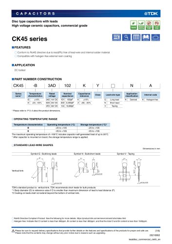 CK45 series
6 Pages

Archived catalogs
 SATA SSD
3 Pages
 CF CARD
3 Pages
 TDK MLCC CATALOG b11
72 Pages
 Wound Type SMD Inductors (Coils)
12 Pages
 Ferrite Magnets FB
27 Pages
 Pin Terminal Type PFC
14 Pages
 E Series
45 Pages
 Feed-back Type EFS
4 Pages
 Piezoelectric Type LTS, TSP
9 Pages
 Chip Beads STD
29 Pages
 Humidity Sensor CHS Series
11 Pages
 Color Video Camera
2 Pages
 Multilayer Chip Beads
27 Pages
 NTC Thermistors SMD
14 Pages
 Multilayer/Q-up MLG0402Q
5 Pages
 SMD NTCG
14 Pages
 Piezoelectric Receiver RU
2 Pages
 EFE300M / EFE400M 300/400
4 Pages
 PTC Thermistors
28 Pages
 Flip Chip Bonder
1 Page
 EMC and RF testing
4 Pages
 RF Integrated Test Systems
12 Pages
 Microwave Absorbers
16 Pages
 Power supplies catalog
24 Pages
 Planar Cores
8 Pages
 Toroidal Cores
2 Pages
 Ferrite Electrodes
4 Pages


![[BHF/BHP] Series for Barcode Printers, and Label Printers](https://img.directindustry.com/pdf/repository_di/34778/bhf-bhp-series-barcode-printers-label-printers-374455_1mg.jpg)


- Temperature probe
- Transformer
- Test cabinet
- Dry transformer
- Surge protector
- Resistance temperature sensor
- Level probe
- Liquid level sensor
- Capacitor
- Current transformer
- Position transducer
- Waterproof temperature sensor
- Power transformer
- Electronic filter
- Current sensor
- Industrial transformer
- Isolation transformer
- Passive electronic filter
- No-contact position sensor
- Solid-state drive