
- Catalogs
- TDK Electronics Europe
- CK45 series


- Products
- Catalogs
- News & Trends
- Exhibitions
CK45 series
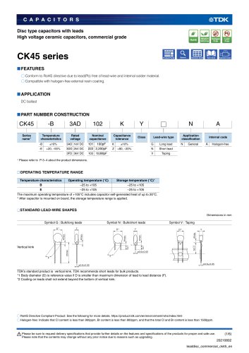
CK45 series
Catalog excerpts
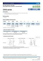
CAPACITORS Disc type capacitors with leads High voltage ceramic capacitors, commercial grade O Conform to RoHS directive due to lead(Pb) free of lead-wire and internal solder material O Compatible with halogen-free external resin coating. □OPERATING TEMPERATURE RANGE Temperature characteristics The maximum operating temperature of +105°C includes capacitor self-generated heat of up to 20°C. * After capacitor is mounted on board, the storage temperature range is applied. □STANDARD LEAD-WIRE SHAPES Dimemsions in mm Symbol G : Bulk/long leads Symbol N : Bulk/short leads Symbol V : Taping Vertical kink TDK’s standard product is vertical kink. TDK recommends short leads for bulk products. *1 Body diameter (D) is reference value if D is smaller than maximum dimension of lead to lead distance (F). *2 Coating on leads shall not extend beyond the bottom of vertical kink. RoHS Directive Compliant Product: See the following for more details. https://product.tdk.com/en/environment/rohs/index.html O Halogen-free: Indicate that Cl content is less than 900ppm, Br content is less than 900ppm, and that the total Cl and Br content is less than 1500ppm. A Please be sure to request delivery specifications that provide further details on the features and specifications of the products for proper and safe use. Please note that the contents may change without any prior notice due to reasons such as upgrading.
Open the catalog to page 1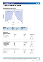
Preheating Peak Item Markings Marking example D dimension: 6.5mm min., temperature characteristic: B Item Markings Marking example D dimension: 6.5mm min., temperature characteristic: E Item Markings Marking example A Please be sure to request delivery specifications that provide further details on the features and specifications of the products for proper and safe use. Please note that the contents may change without any prior notice due to reasons such as upgrading.
Open the catalog to page 2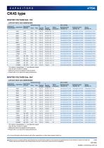
* The values in parentheses "( )" are reference values. Click the part number for details. ** Reference values are applied to bulk products. ***Please refer to p-5 about the taping dimemsions. ♦ For more information about products with other capacitance or other data, please contact us. A Please be sure to request delivery specifications that provide further details on the features and specifications of the products for proper and safe use. Please note that the contents may change without any prior notice due to reasons such as upgrading.
Open the catalog to page 3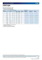
* The values in parentheses "( )" are reference values. Click the part number for details. ** Reference values are applied to bulk products. “Please refer to p-5 about the taping dimemsions. ♦ For more information about products with other capacitance or other data, please contact us. A Please be sure to request delivery specifications that provide further details on the features and specifications of the products for proper and safe use. Please note that the contents may change without any prior notice due to reasons such as upgrading.
Open the catalog to page 4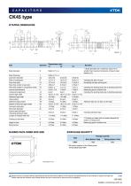
Body diameter *1 Body diameter (D) is reference value if D is smaller than maximum dimension of lead to lead distance (F). Body thickness Lead-wire diameter Including the slant of body Feed hole pitch Excepting the tape splicing part Feed hole center to lead-wire Feed hole center to component center P2 Including the slanting body due to bending lead-wire Lead-to lead distance Measuring point is bottom kink Component alignment Including the slanting body due to bending lead-wire Carrier tape width Adhesive tape width Hole position Adhesive tape position Adhesive tape do not stick out the tape...
Open the catalog to page 5
REMINDERS FOR USING THESE PRODUCTS Before using these products, be sure to request the delivery specifications. SAFETY REMINDERS Please pay sufficient attention to the warnings for safe designing when using this products. REMINDERS Do not use or store in locations where there are conditions such as gas corrosion (salt, acid, alkali, etc.). Before soldering, be sure to preheat components. The preheating temperature should be set so that the temperature difference between the solder temperature and product temperature does not exceed 150°C. Soldering corrections after mounting should be within...
Open the catalog to page 6All TDK Electronics Europe catalogs and technical brochures
 YFF-HC series
5 Pages
 Aluminum electrolytic capacitors
18 Pages
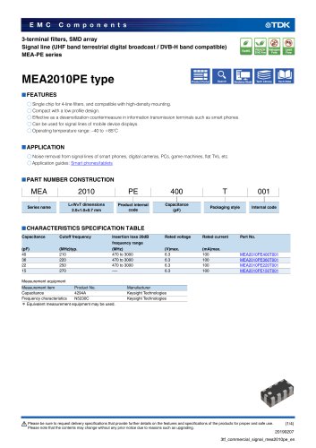

Archived catalogs
 SATA SSD
3 Pages
 CF CARD
3 Pages
 TDK MLCC CATALOG b11
72 Pages
 Wound Type SMD Inductors (Coils)
12 Pages
 Ferrite Magnets FB
27 Pages
 Pin Terminal Type PFC
14 Pages
 E Series
45 Pages
 Feed-back Type EFS
4 Pages
 Piezoelectric Type LTS, TSP
9 Pages
 Chip Beads STD
29 Pages
 Humidity Sensor CHS Series
11 Pages
 Color Video Camera
2 Pages
 Multilayer Chip Beads
27 Pages
 NTC Thermistors SMD
14 Pages
 Multilayer/Q-up MLG0402Q
5 Pages
 SMD NTCG
14 Pages
 Piezoelectric Receiver RU
2 Pages
 EFE300M / EFE400M 300/400
4 Pages
 PTC Thermistors
28 Pages
 Flip Chip Bonder
1 Page
 EMC and RF testing
4 Pages
 RF Integrated Test Systems
12 Pages
 Microwave Absorbers
16 Pages
 Power supplies catalog
24 Pages
 Planar Cores
8 Pages
 Toroidal Cores
2 Pages
 Ferrite Electrodes
4 Pages


![[BHF/BHP] Series for Barcode Printers, and Label Printers](https://img.directindustry.com/pdf/repository_di/34778/bhf-bhp-series-barcode-printers-label-printers-374455_1mg.jpg)


- Transformer
- Dry transformer
- Encapsulated transformer
- Electronic filter
- Isolation transformer
- Passive electronic filter
- Contactor
- Diode
- Solid-state drive
- Low-pass electronic filter
- TDK SMD capacitor
- Internal solid-state drive
- Power capacitor
- TDK film capacitor
- TDK RoHS capacitor
- Industrial solid-state drive
- Current capacitor
- High-voltage diode