- Catalogs
- TB Wood s Electronic - Woodsdrives.com
- Clutch Product Catalog
Clutch Product Catalog
1 /32Pages

Clutch Product Catalog
1 /32Pages
Catalog excerpts

ALTRA INDUSTRIAL MOTION An Altra Industrial Motion Company
Open the catalog to page 1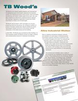
TB Wood’s is an industry leading designer and manufacturer of mechanical power transmission equipment for industrial control. Our mechanical product lines include: clutch and brake, synchronous and belted variable speed drives; grid, disc, jaw, gear coupling and elastomeric coupling products; sheaves and bushings. Registered trademarks include Sure-Flex®, Dura-Flex®, G-Flex®, and QT Bushings®. TB Wood’s was founded in 1857 and began as a foundry producing wood burning stoves. Our company’s tradition of product innovation started early. Wood’s entered the power transmission industry at the turn...
Open the catalog to page 2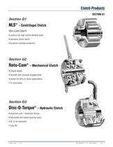
Clutch Products NLS® - Centrifugal Clutch • cushion for high inertia starting loads • dampens shock starts • systems overload protection RotO-Cam® - Mechanical Clutch simple design smooth cam actuated engagements sealed for dirty or dusty applications DiSC-O-Torque® - Hydraulic Clutch minimum size / maximum torque lubricated and sealed bearing types long life
Open the catalog to page 3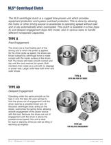
NLS® Centrifugal Clutch The NLS centrifugal clutch is a rugged time-proven unit which provides equipment protection and system overload protection. This is done by allowing the motor or other driving source to accelerate to operating speed without load and to slip automatically when overloaded. This clutch is available in a free (type A) and delayed engagement (type AD) model, also in various sizes to handle different horsepower capacities. Free Engagement The shoes are a free floating part of the driving unit to which the power is applied. As the driver picks up speed, the shoes are forced outward...
Open the catalog to page 4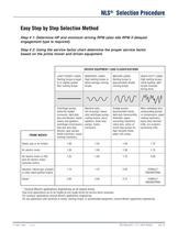
NLS® Selection Procedure Easy Step by Step Selection Method Step # 1: Determine HP and minimum driving RPM (also idle RPM if delayed engagement type is required). Step # 2: Using the service factor chart determine the proper service factor based on the prime mover and driven equipment. * Consult Wood's applications engineering on all engine drives. Dual drive applications are to be treated as two single drives for service factor purposes. For conveyor applications consult Wood's applications engineering. For any application with extremes in inertia, starting torque, or questionable equipment,...
Open the catalog to page 5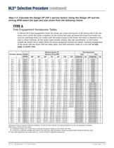
NLS® Selection Procedure (continued) Step # 3: Calculate the Design HP (HP x service factor). Using the Design HP and the driving RPM select the type and size clutch from the following charts. Free Engagement Horsepower Tables In Wood's NLS free engagement clutch the shoes are a free-moving part of the driving half of the two- piece unit to which the power is applied. As the driving half picks up speed the shoes are forced out- ward by centrifugal force into contact with the inside surface of the driven half which is attached to the load or driven machine. As the shoes make smooth contact, they...
Open the catalog to page 6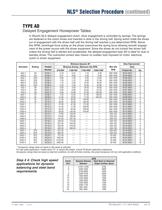
NLS® Selection Procedure (continued) Delayed Engagement Horsepower Tables In Wood's NLS delayed engagement clutch, shoe engagement is controlled by springs. The springs are fastened to the clutch shoes and inserted in slots in the driving half. Spring action holds the shoes out of engagement with the driven half until the driving half reaches a pre-determined RPM. Above this RPM, centrifugal force acting on the shoes overcomes the spring force allowing smooth engage- ment of the power source with the driven equipment. Since the shoes do not contact the driven half unless the driving half is started...
Open the catalog to page 7
NLS® Selection Procedure (continued) Step # 5: Check bore size and available space envelope. Free Engagement Delayed Engagement
Open the catalog to page 8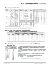
NLS® Selection Procedure (continued) Bore and keyseat information Step # 7: If inertia is not known or clutch speed is not listed on WR2 chart. ACCELERATION TABLE Energy Capacity Maximum allowable acceleration time in seconds can be calculated by dividing the energy capacity in horsepower-seconds by the clutch design If actual acceleration time exceeds the maximum allowable time, a larger clutch should be selected or if the start-up frequency is more than 1 every Example: A12A-3 is rated at 533 hp @ 1750 with an energy capacity of 3400 3400 Horsepower-seconds = 6.4 seconds maximum allowable acceleration...
Open the catalog to page 9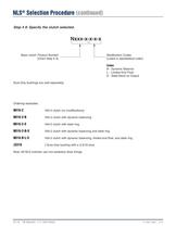
NLS® Selection Procedure (continued) Step # 8: Specify the clutch selected. Basic clutch Product Number Sure-Grip bushings are sold separately. Modification Codes (Listed in alphabetical order) S - Steel Band on Output Ordering examples: 16A-2 clutch with dynamic balancing 16A-2 clutch with steel ring 16A-2 clutch with dynamic balancing and steel ring 16A-2 clutch with dynamic balancing, limited end float, and steel ring J Sure-Grip bushing with a 3-3/16 bore Note: AN NLS clutches use non-asbestos shoe linings.
Open the catalog to page 10
NLS® Selection Procedure (continued) From Clutches to Couplings or Belted Drives to Electronic Controls Power Transmission Components to Suit Your Needs. With Wood's large range of products and time in the business since 1857, we are able to supply the correct components, as well as the experience necessary to properly apply them. For technical assistance on any Wood's product
Open the catalog to page 11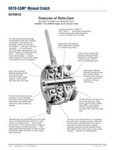
ROTO-CAM® Manual Clutch Manually Controlled Cam Operated Clutch Available in four different types, one to suit your need. The cam-supported ball bearings incorporated in Roto-Cam Clutches lubricated, sealed, Conrad-Type, class ABEC-1—with high thrust load The entire load—and only load—on these bearings is the Belleville spring force ... a constant, controlled, conservative loading ... assures highly reliable B-10 bearing life values for thousands of hours of operation. (CA—Type 1)... with integral, ball bearing mounted sheave and direct hand-lever Heavy-duty, steel pressure plate is faced with...
Open the catalog to page 12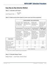
ROTO-CAM® Selection Procedure Easy Step by Step Selection Method Step # 1: Calculate Load Torque. Step # 2: Select service factor based on prime mover and driven equipment * If a type 4 clutch is selected, a hardened drive cup is recommended. Step # 3: Calculate Design Torque. Design Torque = Load Torque x Service Factor
Open the catalog to page 13All TB Wood s Electronic - Woodsdrives.com catalogs and technical brochures
 V-Belt Drives
231 Pages
 ndustrial Couplings
12 Pages
 Flexible Disc Couplings
52 Pages
 Belt Drives, Sheaves and Couplings
498 Pages
 Premium V-Belt Drives Catalog
68 Pages


- Power transmission belt
- SARRALLE flexible coupling
- SARRALLE shaft coupling
- Rubber strip
- SARRALLE flange coupling
- Metal stand
- Torque coupling
- SARRALLE rigid coupling
- Friction clutch
- SARRALLE sleeve coupling
- Motor shaft coupling
- Trapezoidal belt
- Steel bracket
- Double-disc coupling
- Industrial coupling
- SARRALLE pump coupling
- SARRALLE compensating coupling
- Toothed pulley
- Elastomer coupling
- Groove pulley