Cronos series
1 /20Pages

Cronos series
1 /20Pages
Catalog excerpts

PRESSURE REGULATORS Type Cronos Process Management
Open the catalog to page 1
Cronos Regulators Pressure Regulators This series of “Top-Entry” appliances was designed to meet a wide range of applications, offering easy maintenance combined with compact size. To achieve this, we introduced a new modularity concept which, combined with our experience and TARTARINI technologies developed in axial flow regulators, has enabled us to build a wide range of versions to the same design philosophy. These are, in brief, the features of the project: • MODULARITY Modularity is ensured by a central cross-shaped body, which is the system’s key component, enabling either horizontal or...
Open the catalog to page 2
Cronos Regulators Configurations CCB Regulator + Monitor + Shut-off ID-ABREVIATIONS Horizontal flow Regulator + Monitor + Shut-off SRS silenced solutions have a widened output flange. Also available: version with widened output, but without a built-in silencer. DN 25 ANSI 150 horizontal flow regulator with SRS silencer: DN 25 ANSI 150 horizontal flow regulator with widened output:
Open the catalog to page 3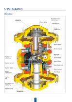
Cronos Regulators Operation Regulated pressure chamber (Pd) MONITOR Monitor spring Diaphragm unit Monitor shutter SHUT-OFF Regulator and monitor seat Shut-off spring Shut-off shutter Regulator seal pad Shut-off reset shaft Regulator shutter Shut-off seal pad Moving chamber (Pm) Shut-off seat Diaphragm unit Regulated pressure chamber (Pd) Regulator spring
Open the catalog to page 4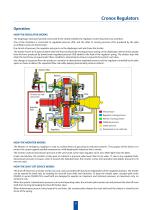
Cronos Regulators Operation HOW THE REGULATOR WORKS The Diaphragm Unit (permanently connected to the shutter) divides the regulator control head into two chambers. One of the chambers is connected to regulated pressure (Pd), and the other to moving pressure (Pm) produced by the pilot according to pressure downstream. Due to lack of pressure, the regulator spring acts on the diaphragm unit and closes the shutter. The shutter moves to its open position when the force produced by moving pressure acting on the diaphragm unit becomes greater than the force produced by downstream regulated pressure...
Open the catalog to page 5
Cronos Regulators Features Applications CRONOS series regulators are used in reduction, distribution and conveying stations of suitably filtered natural gas. They can also be used for air, propane, butane, LPG, city gas, nitrogen, carbon dioxide and hydrogen. Technical Features Flange rating PN 16 - ANSI 150 Allowable pressure Inlet pressure range Set range Min.operating differential pres. Flange rating PN 25/40 - ANSI 300/600 Allowable pressure Inlet pressure range Set range Min.operating differential pres. Functional Features Accuracy class Lock-up pressure class Class of lock-up pressure zone...
Open the catalog to page 6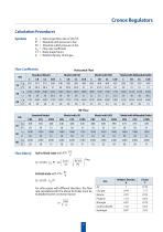
Cronos Regulators Calculation Procedures Symbols Natural gas flow rate in Stm3/h Absolute inlet pressure in bar Absolute outlet pressure in bar Flow rate coefficient Body shape factor Relative density of the gas Horizontal Flow Standard Model Model with Widended Outlet Standard Model Model with Widended Outlet Sub-critical state with P2> P1 Critical state with P2≤ 2 Q = 0.525 ⋅ Cg⋅ P1 Carbon dioxide For other gases with different densities, the flow rate calculated with the above formulas must be multiplied by the correction factor:
Open the catalog to page 7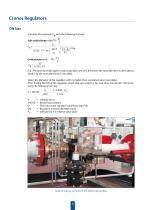
Cronos Regulators DN Size Calculate the required Cg with the following formula: P1 2 Sub-critical state with P2> Q Critical state with Cg = N.B. The above formulas apply to natural gas flow rate only. If the flow rate value (Q) refers to other gasses, divide it by the correction factor F (see table). Select the diameter of the regulator with Cg higher than calculated value (see table). After finding the DN of the regulator, check that gas speed on the seat does not exceed 120 m/sec, using the following formula: V = 345.92 ⋅ Velocity (m/s) Numerical constant Flow rate under standard conditions...
Open the catalog to page 8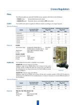
Cronos Regulators Pilots The following pilots are used with CRONOS series regulator with built-in shut-off device: • OS/80X series: Spring loaded pneumatic device • OS/80X-PN series: Pneumatic device controlled by PRX series pilots The OS/80X series pilot is supplied in different models according to set ranges required. Technical Features Model Servomotor Body Resistance (bar) OS/80X Servomotor body: Diaphragm: O-ring: OS/80X-BP, OS/80X-BPA-D OS/80X-MPA-D, OS/80X-APA-D Fabric NBR+PVC/Nitrile rubber NBR Rubber OS/84X, OS/88X Servomotor body: Lip seal: O-ring: Aluminim Steel Brass Teflon (PTFE)...
Open the catalog to page 9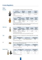
Cronos Regulators Pilots PS/ Series Cronos series regulators are equipped with the PS/ or PRX/ series pilots. Application Body and Covers Material 1/4” NPT female threaded connections Application Regulator or Monitor Operating Monitor Regulator Body and Covers Material Steel 1/4” NPT female threaded connections All PS/ series pilots are supplied with a filter (5µ filtering degree) and built-in pressure stabilizer, with the exception of pilots PSO/79 and PSO/80. Application Regulator or Monitor Operating Monitor Regulator Body and Covers Material Steel 1/4” NPT female threaded connections The...
Open the catalog to page 10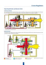
Cronos Regulators Operating Monitor and Booster Valve OPERATING MONITOR The “operating monitor” has two functions: under normal duty, it reduces pressure in the intermediate section between the two regulators, but, if the main regulator fails, it comes into operation as an emergency regulator. Operating Monitor To the connection on the body rear side BOOSTER VALVE The booster valve is fitted on the monitor-regulator system which branches off from the monitor drive pressure circuit, so that the monitor operates more quickly. PS/79 Monitor PRX/131 A A To the connection on the body rear side Inlet...
Open the catalog to page 11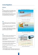
Cronos Regulators Silencers SR Beyond this speed could be necessary to act on the noise generated by the expansion cone usually installed downstream of the regulator. This silencer is fitted near the regulator shutter and is highly efficient up to a theoretical speed of 80 m/s calculated at the outlet flange. Built-in multi-path or split-flow silencer Noise of non silenced regulator db(a) Mixed split-flow, multi-stage silencer Multi-stage section Multi-path section The SRS silencer consists of an SR silencer plus a widened outlet flange in which a second silencer is fitted. The second silencer...
Open the catalog to page 12All Tartarini catalogs and technical brochures
 Type A/100
8 Pages
 Pressure Regulators Type M
20 Pages
 FL series
20 Pages
 971
9718 Pages
 V Relief Valves - Bulletin
8 Pages
 RLC/20
2 Pages
 R series
8 Pages
 Type M
2 Pages
 Cronos Pressure Regulators
2 Pages
 natrul gas technologie
2 Pages


- Manual valve
- Control valve
- Pneumatic valve
- Regulating valve
- On/off valve
- Lever valve
- Gas valve
- Filter with cartridge
- Pneumatically-operated valve
- Butterfly valve
- Single-stage pressure regulator
- Gate valve
- Heat exchanger unit
- Industrial pressure limiter
- Valve with membrane
- Membrane regulator
- Air valve
- Flow control valve