- Catalogs
- Tapeswitch
- PSCU/1 Control Uni
PSCU/1 Control Uni
1 /2Pages
PSCU/1 Control Uni
1 /2Pages
Catalog excerpts
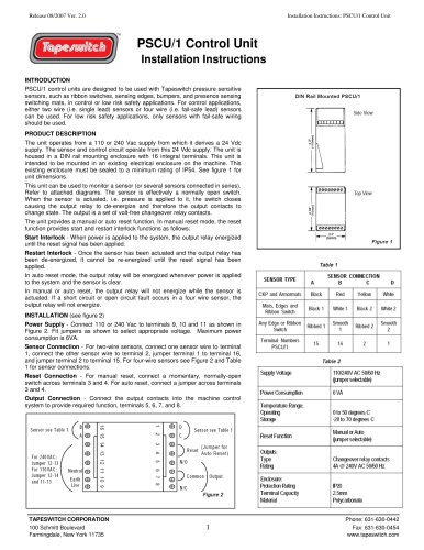
Installation Instructions: PSCU/1 Control Unit PSCU/1 Control Unit Installation Instructions INTRODUCTION PSCU/1 control units are designed to be used with Tapeswitch pressure sensitive sensors, such as ribbon switches, sensing edges, bumpers, and presence sensing switching mats, in control or low risk safety applications. For control applications, either two wire (i.e. single lead) sensors or four wire (i.e. fail-safe lead) sensors can be used. For low risk safety applications, only sensors with fail-safe wiring should be used. PRODUCT DESCRIPTION The unit operates from a 110 or 240 Vac supply from which it derives a 24 Vdc supply. The sensor and control circuit operate from this 24 Vdc supply. The unit is housed in a DIN rail mounting enclosure with 16 integral terminals. This unit is intended to be mounted in an existing electrical enclosure on the machine. This existing enclosure must be sealed to a minimum rating of IP54. See figure 1 for unit dimensions. This unit can be used to monitor a sensor (or several sensors connected in series). Refer to attached diagrams. The sensor is effectively a normally open switch. When the sensor is actuated, i.e. pressure is applied to it, the switch closes causing the output relay to de-energize and therefore the output contacts to change state. The output is a set of volt-free changeover relay contacts. The unit provides a manual or auto reset function. In manual reset mode, the reset function provides start and restart interlock functions as follows: Start Interlock - When power is applied to the system, the output relay energized until the reset signal has been applied. Restart Interlock - Once the sensor has been actuated and the output relay has been de-energized, it cannot be re-energized until the reset signal has been applied. In auto reset mode, the output relay will be energized whenever power is applied to the system and the sensor is clear. In manual or auto reset, the output relay will not energize while the sensor is actuated. If a short circuit or open circuit fault occurs in a four wire sensor, the output relay will not energize. Power Supply - Connect 110 or 240 Vac to terminals 9, 10 and 11 as shown in Figure 2. Fit jumpers as shown to select appropriate voltage. Maximum power consumption is 6VA. Sensor Connection - For two-wire sensors, connect one sensor wire to terminal 1, connect the other sensor wire to terminal 2, jumper terminal 1 to terminal 16, and jumper terminal 2 to terminal 15. For four-wire sensors see Figure 2 and Table 1 for sensor connections. Reset Connection - For manual reset, connect a momentary, normally-open switch across terminals 3 and 4. For auto reset, connect a jumper across terminals 3 and 4. Output Connection - Connect the output contacts into the machine control system to provide required function, terminals 5, 6, 7, and 8. TAPESWITCH CORPORATION 100 Schmitt Boulevard Farmingdale, New York 11735
Open the catalog to page 1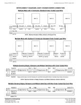
Installation Instructions: PSCU/1 Control Unit INTERCONNECT DIAGRAMS, DAISY CHAINED/SERIES CONNECTION Multiple Mats with 4 Conductor Standard Color Coded Lead Wire YELLOW WHITE NOTE: Maximum Number of Mats Limited to 100 Square Feet Multiple Mats with Optional 2 Conductor Standard Color Coded Lead Wire BLACK WHITE Multiple Sensing Edges, Bumpers and Ribbon Switches with Color Coded Wire Edge/sensor 1 W HITE BLACK W HITE W HITE Edge/sensor N BLACK Edges and Bumpers Can Be Ordered with Lead Wire Exiting Both Ends to Facilitate Easy Series Connection NOTE: Maximum Number of Edges, Bumpers, and Ribbon...
Open the catalog to page 2All Tapeswitch catalogs and technical brochures
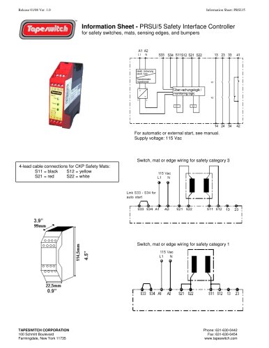
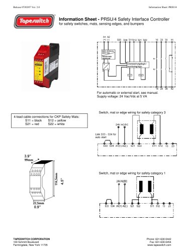
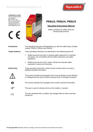 PRSU/2, PRSU/4, PRSU/5
14 Pages

Archived catalogs
 Safety & Signaling Products
12 Pages
 Light Curtain Catalog
12 Pages
 Safety Interlock Catalog
20 Pages
 Short Form Catalog
12 Pages
 Switch products
24 Pages
 Sensing Edge Catalog
15 Pages
 Sensing Bumper Catalog
10 Pages
 Safety and Sensing Mat Catalog
18 Pages
 Safety Interface Module Catalog
12 Pages
 Light Curtains & Laser Scanner
14 Pages
 Safety & Signal Mats Catalog
19 Pages


- Force sensor
- Tension/compression force transducer
- Single-pole switch
- Strain gauge force sensor
- Technology switch
- Compression force transducer
- Safety electric switch
- Rototherm electric pedal
- IP67 switch
- Rubber mat
- Touch switch
- Metal switch
- Polymer mat
- Hermetic switch
- Interface module
- Button type resistive load cell
- Industrial switch
- Lever switch
- Heavy-duty switch
- Stainless steel switch