- Catalogs
- Tapeswitch
- PRSU/2, PRSU/4, PRSU/5
PRSU/2, PRSU/4, PRSU/5
1 /14Pages
PRSU/2, PRSU/4, PRSU/5
1 /14Pages
Catalog excerpts

PRSU Series, Operating Instructions Manual (Revision 1.0) TAPESWITCH CORP. 100 Schmitt Boulevard Farmingdale New York 11735 Phone: 800-234-8273 Fax: 631-630-0454 [email protected] www.tapeswitch.com PRSU/2, PRSU/4, PRSU/5 Operating Instructions Manual Safety controllers for safety mats and sensing edge products This operating instruction shall familiarize you with the safety relay controller models: PRSU/2, PRSU/4 and PRSU/5. Target Audience These operating instructions are addressed to the following personnel: Skilled personnel who plan or develop safety equipment for machines and plants, who are familiar with the safety instructions and safety regulations. Skilled personnel who build, install, maintain and operate safety equipment in plants and machinery. These operating instructions contain several symbols which are used to highlight important information: This symbol indicates text passages which must absolutely be paid attention to. Disregarding may lead to serious personal injury or damage to property. This symbol indicates text passages which contain important information. This sign is used to indicate actions by the installer or operator. This sign illustrates that a condition has changed after an action has been carried out. © Copyright (2021) All rights reserved. Changes, which serve technical improvements are reserved.
Open the catalog to page 1
PRSU Series, Operating Instructions Manual (Revision 1.0) Safety Warning The safety relays PRSU/2, PRSU/4 and PRSU/5 are intended for the use with: ■ Single or dual-channel capability safety mats. ■ Single or dual-channel capability sensing edges, bumpers or ribbon switches. Operator and asset protection are only guaranteed if the safety relay is operated according to its intended purpose and within the limits stated in its specification. Please pay attention to the following points: ■ The device must be wired and operated by specialized staff who are familiar with the current regulations for...
Open the catalog to page 2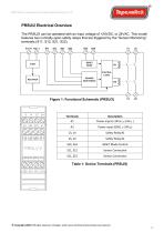
PRSU Series, Operating Instructions Manual (Revision 1.0) Table 1: Device Terminals (PRSU/2) © Copyright (2021) All rights reserved. Changes, which serve technical improvements are reserved.
Open the catalog to page 3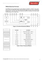
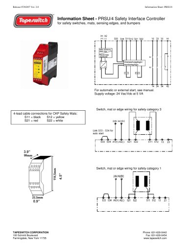
PRSU Series, Operating Instructions Manual (Revision 1.0) The PRSU/4 can be operated with an input voltage of +24VDC, or 24VAC. This model features three normally-open safety relays that are triggered by the "Sensor Monitoring” terminals (S11, S12, S21, S22). This model also features an additional normally-closed auxiliary relay (not for safety use). Table 2: Device Terminals (PRSU/4) © Copyright (2021) All rights reserved. Changes, which serve technical improvements are reserved.
Open the catalog to page 4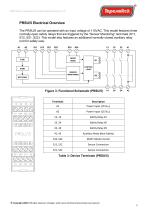
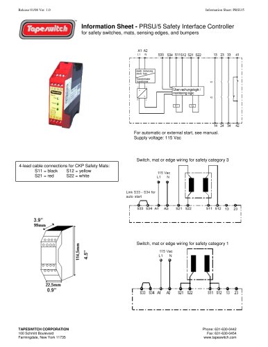
PRSU Series, Operating Instructions Manual (Revision 1.0) The PRSU/5 can be operated with an input voltage of 115VAC. This model features three normally-open safety relays that are triggered by the "Sensor Monitoring” terminals (S11, S12, S21, S22). This model also features an additional normally-closed auxiliary relay (not for safety use). Table 3: Device Terminals (PRSU/5) © Copyright (2021) All rights reserved. Changes, which serve technical improvements are reserved.
Open the catalog to page 5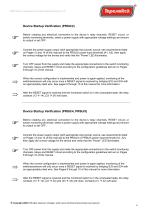
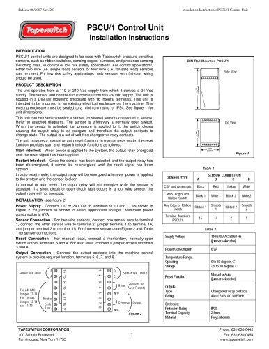
PRSU Series, Operating Instructions Manual (Revision 1.0) Device Startup Verification (PRSU/2) Before creating any electrical connection to the device´s relay channels, RESET circuit, or switch monitoring terminals, select a power supply with appropriate voltage settings and ensure its output is set OFF. Connect the power supply output (with appropriate input power source; see requirements listed on Pages 13 and 14 of this manual) to the PRSU/2 power input terminals (A1, A2), then apply the correct voltage for the device and verify that the “Power” LED illuminates. Turn OFF power from the supply...
Open the catalog to page 6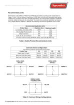
PRSU Series, Operating Instructions Manual (Revision 1.0) Performance of the PRSU/2, PRSU/4 and PRSU/5 are limited according to the values listed on Pages 13 and 14 of this manual. In particular, a 200Q limit on short-circuit (actuated state) series resistance is required for four-wire, fail-safe applications. The overall series resistance of different products, cables and layouts can vary greatly. To ensure that a particular application will require only a single PRSU/2, PRSU/4 or PRSU/5, the following rule-of-thumb guidelines can be used: Recommended Application Limits Table 4: Safety Product...
Open the catalog to page 7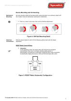
PRSU Series, Operating Instructions Manual (Revision 1.0) Device Mounting and Unmounting Mechanical Mounting All units should be DIN-rail mounted and/or panel-mounted in an enclosure rated at IP 54 or better. Dust and dampness could lead to malfunction. ▪ There is a notch on the rear of the unit for DIN-Rail attachment. Figure 4: DIN Rail Mounting Detail Electrical Connections Wire the device based on which of the following options best suits the target application: RESET Mode Control Wiring: 1. Automatic: In this operating mode, the output relay coils will become energized automatically if and...
Open the catalog to page 8
PRSU Series, Operating Instructions Manual (Revision 1.0) 2. Manual: In this operating mode, the output relay coils will de-energize upon the closure of conductors within the monitored sensor/switch system. The coils will not energize again until the closure is broken and a RESET signal is manually generated by the operator (via a mechanical N.O. pushbutton or switch). Figure 6: RESET Mode (Manual) Configuration Conditional: In this operating mode, the RESET signal cannot propagate unless all of the following conditions are met: - The contacts have opened in the monitored sensor/switch. The machine...
Open the catalog to page 9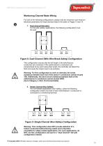
PRSU Series, Operating Instructions Manual (Revision 1.0) Monitoring Channel Mode Wiring For both of the following configurations, please note the maximum and minimum electrical parameters for these devices listed in the table on Pages 13 and 14. 1. Dual channel (fail-safe): For fail-safe (safety) applications, the following configuration must be used: Figure 8: Dual-Channel (With Wire-Break Safety) Configuration This configuration ensures that the full length of all switch/sensor conductors are monitored. If the switch/sensor’s conductors are compromised at any point along their length, the...
Open the catalog to page 10All Tapeswitch catalogs and technical brochures
 PSCU/1 Control Uni
2 Pages

Archived catalogs
 Safety & Signaling Products
12 Pages
 Light Curtain Catalog
12 Pages
 Safety Interlock Catalog
20 Pages
 Short Form Catalog
12 Pages
 Switch products
24 Pages
 Sensing Edge Catalog
15 Pages
 Sensing Bumper Catalog
10 Pages
 Safety and Sensing Mat Catalog
18 Pages
 Safety Interface Module Catalog
12 Pages
 Light Curtains & Laser Scanner
14 Pages
 Safety & Signal Mats Catalog
19 Pages


- Force sensor
- Tension/compression force transducer
- Single-pole switch
- Strain gauge force sensor
- Technology switch
- Compression force transducer
- Safety electric switch
- Electronic pedal
- IP67 switch
- Rubber mat
- Touch switch
- Metal switch
- Polymer mat
- Hermetic switch
- Interface module
- Button type resistive load cell
- Industrial switch
- Lever switch
- Heavy-duty switch
- Stainless steel switch