- Catalogs
- Tapeswitch
- PCU Programmable Safety Control Unit
PCU Programmable Safety Control Unit
1 /93Pages
PCU Programmable Safety Control Unit
1 /93Pages
Catalog excerpts

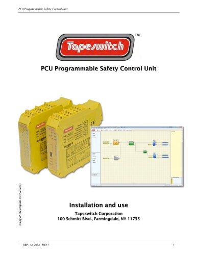
PCU Programmable Safety Control Unit (Copy of the original instructions) PCU Programmable Safety Control Unit Installation and use Tapeswitch Corporation 100 Schmitt Blvd., Farmingdale, NY 11735
Open the catalog to page 1
PCU Programmable Safety Control Unit
Open the catalog to page 2
PCU Programmable Safety Control Unit
Open the catalog to page 3
PCU Programmable Safety Control Unit
Open the catalog to page 4
PCU Programmable Safety Control Unit
Open the catalog to page 5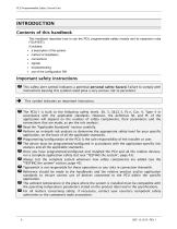
PCU Programmable Safety Control Unit INTRODUCTION Contents of this handbook This handbook describes how to use the PCU programmable safety module and its expansion units ("SLAVES"); it includes: • a description of the system • method of installation • connections • signals • troubleshooting • use of the configuration SW Important safety instructions This safety alert symbol indicates a potential personal safety hazard. Failure to comply with instructions bearing this symbol could pose a very serious risk to personnel. This symbol indicates an important instruction. PCU/1 is built to the following...
Open the catalog to page 6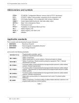
PCU Programmable Safety Control Unit PCM = PCUMCM/1 Configuration Memory: memory chip for PCU/1 (accessory) PCI = PCUECI/1 Safety Communication: proprietary bus for expansion units PSD = PCU Safety Designer: PCU configuration SW running in Windows OSSD = Output Signal Switching Device: solid state safety output MTTFd = Mean Time to Dangerous Failure PFHd = Probability of a dangerous failure per Hour SIL = Safety Integrity Level SILCL = Safety Integrity Level Claim Limit PCU complies with the following European Directives: • 2004/108/EC "Electromagnetic Compatibility Directive" and is built to...
Open the catalog to page 7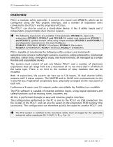
PCU Programmable Safety Control Unit OVERVIEW PCU is a modular safety controller. It consists of a master unit (PCU/1), which can be configured using the PSD graphic interface, and a number of expansion units connected to the PCU/1 via the proprietary PCI bus. The PCU/1 can also be used as a stand-alone device. It has 8 safety inputs and 2 independent programmable dual channel outputs. The following expansions are available: I/O expansions (PCU8I2/1), input only expansions (PCU8IE/1, PCUEU/1 and PCU16IE/1), output only expansions (PCU2E/1 and PCU4E/1), guided contact safety relay output modules...
Open the catalog to page 8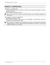
PCU Programmable Safety Control Unit • CD-ROM containing the free PSD SW, this PDF multi-language handbook and other product literature. • Multi-language installation sheet. ^ NB: the rear panel PCI connector and PCM memory can be ordered separately as accessories. The expansion units are supplied with: • Multilingual Installation sheet. • Rear panel PCI connector (not present in the PCU2SR/1 and PCU4SR/1 which are connected via terminal blocks only). ^ NB: to install an expansion unit (excluding relays) you will need the PCI connector supplied with the unit plus another PCI for the connection...
Open the catalog to page 9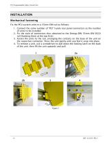
PCU Programmable Safety Control Unit Fix the PCU system units to a 35mm DIN rail as follows: 1. Connect the same number of "PCI" 5-pole rear panel connectors as the number of units to be installed. 2. Fix the train of connectors thus obtained to the Omega DIN 35mm (EN 5022) rail (hooking them at the top first). 3. Fasten the units to the rail, arranging the contacts on the base of the unit on the respective connector. Press the unit gently until you feel it snap into place. 4. To remove a unit, use a screwdriver to pull down the locking latch on the back of the unit; then lift the unit upwards...
Open the catalog to page 10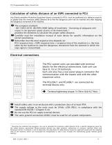
PCU Programmable Safety Control Unit Any Electro-sensitive Protective Equipment device connected to PCU, must be positioned at a distance equal to or greater than the minimum safety distance S so that the dangerous point can be reached only after stopping the dangerous movement of the machine. - ISO 1 3855:201 0- (EN 999:2008) Safety of machinery - Positioning of safeguards with respect to the approach speeds of parts of the human body. 1 provides the elements to calculate the proper safety distance. ! Carefully read the installation manual of each device for specific information on the correct...
Open the catalog to page 11
PCU Programmable Safety Control Unit ^ Wire size range: AWG 1 2^30, (solid/stranded) (UL). ^ Use 60/75°C copper (Cu) conductor only. ^ We recommend the use of separate power supplies for the safety module and for other electrical power equipment (electric motors, inverters, frequency converters) or other sources of disturbance. ^ Cables used for connections of longer than 50m must have a cross-section of at least 1mm2 (AWG16).
Open the catalog to page 12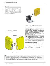
PCU Programmable Safety Control Unit USB input The PCU master PCU/1 includes a USB 2.0 connector for connection to a Personal Computer where the PSD (PCU Safety Designer) configuration SW resides. A USB cable of the correct size is available as an accessory (PCUCUSBC/1). Figure 2 - USB 2.0 front panel connector PCU Configuration Memory (PCM) TECHNICAL DATA LABEL A backup memory, called PCM (optional) can be installed in the PCU master PCU/1 and used to save the SW configuration parameters. The PCM is written each time a new project is sent from the PC to the PCU/1. Always switch the PCU/1 off...
Open the catalog to page 13
PCU Programmable Safety Control Unit RESTORE function If the PCU/1 unit is damaged, you can replace it with a new one; having already saved all the configurations on the PCM, all you need to do is insert the PCM in the new PCU/1 and switch on the PCU system that will immediately load the backup configuration. In this way, the work interruptions will be minimized. The LOAD and RESTORE functions can be disabled via SW. (see Figure 29) In order to be used, the expansion units must be addressed at the time of installation (see the NODE SEL section). Each time PCM is used, carefully check that the...
Open the catalog to page 14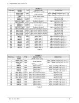
PCU Programmable Safety Control Unit
Open the catalog to page 15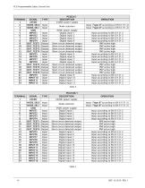
PCU Programmable Safety Control Unit
Open the catalog to page 16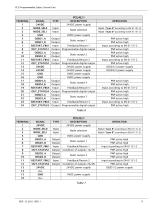
PCU Programmable Safety Control Unit
Open the catalog to page 17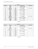
PCU Programmable Safety Control Unit
Open the catalog to page 18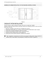
PCU Programmable Safety Control Unit EXAMPLE OF CONNECTION OF PCU TO THE MACHINE CONTROL SYSTEM The PCU system is able to detect the faults that occurs in each own module. Anyway to have the system perfect operation perform the following checks at start up and at least every one year: 1. Operate a complete system TEST (see "TESTING the system") 2. Verify that all the cables are correctly inserted and the terminal blocks well screwed. 3. Verify that all the leds (indicators) light on correctly. 4. Verify the positioning of all the sensors connected to PCU. 5. Verify the correct fixing of PCU to...
Open the catalog to page 19All Tapeswitch catalogs and technical brochures
 PSCU/1 Control Uni
2 Pages
 PRSU/2, PRSU/4, PRSU/5
14 Pages
Archived catalogs
 Safety & Signaling Products
12 Pages
 Light Curtain Catalog
12 Pages
 Safety Interlock Catalog
20 Pages
 Short Form Catalog
12 Pages
 Switch products
24 Pages
 Sensing Edge Catalog
15 Pages
 Sensing Bumper Catalog
10 Pages
 Safety and Sensing Mat Catalog
18 Pages
 Safety Interface Module Catalog
12 Pages
 Light Curtains & Laser Scanner
14 Pages
 Safety & Signal Mats Catalog
19 Pages


- Force sensor
- Tension/compression force transducer
- Single-pole switch
- Strain gauge force sensor
- Technology switch
- Compression force transducer
- Safety electric switch
- Rototherm electric pedal
- IP67 switch
- Rubber mat
- Touch switch
- Metal switch
- Polymer mat
- Hermetic switch
- Interface module
- Button type resistive load cell
- Industrial switch
- Lever switch
- Heavy-duty switch
- Stainless steel switch