- Catalogs
- Taon Hydraulik Komponenter ApS
- K3VL Kawasaki Piston Pumps
K3VL Kawasaki Piston Pumps
1 /67Pages

K3VL Kawasaki Piston Pumps
1 /67Pages
Catalog excerpts
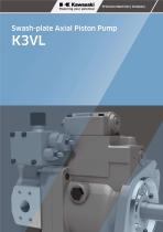
Precision Machinery Company Swash-plate Axial Piston Pump
Open the catalog to page 1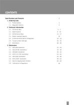
2-4. Radial Loading Capacity 18 2-5. Functional Description of Regulator 19 - 23 2-6. Torque Limiter Settings 24 - 25 3-7. Electric Displacement Control 63 - 64
Open the catalog to page 2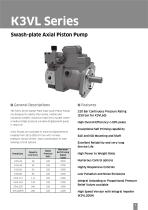
K3VL Pumps are available in nominal displacements ranging from 28 to 200 cm3/rev with various pressure, torque limiter, and a combination of load sensing control options. ■ General Descriptions The K3VL Series Swash Plate Type Axial Piston Pumps are designed to satisfy the marine, mobile and industrial markets industrial machinery market where a medium/high pressure variable displacement pump is required. 320 Bar Continuous Pressure Rating (250 bar for K3VL60) High Overall Efficiency (>90% peak) Exceptional Self Priming capability Excellent Reliability and very long Service Life High Power to...
Open the catalog to page 3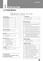
Ordering Code 1-1 Pump OptionsK3VL 80 0 /B - 1 0 R S S - LO 0 /1-H1 K3VL Series Pump- Maximum Displacement
Open the catalog to page 4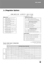
Regulator Type
Open the catalog to page 5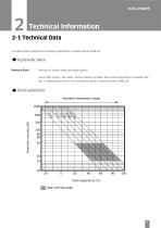
Technical Information 2-1 Technical Data For applications outside the following parameters, please consult KPM UK. Pressure Fluid Mineral oil, polyol ester and water glycol. Use a high quality, anti-wear, mineral based hydraulic fluid when the pressure exceeds 206 bar. In applications where fire resistant fluids are required consult KPM UK. fluid temperature (°C) | | Ideal working range
Open the catalog to page 6
2-1 Technical Data (cont)♦ Filtration & Contamination Control Filtration The most important means to prevent premature damage to the pump and associated equipment and to extend its working life, is to ensure that hydraulic fluid contamination control of the system is working effectively. This begins by ensuring that at the time of installation that all piping, tanks etc. are rigorously cleaned in a sanitary way. Flushing should be provided using an off line filtration system and after flushing the filter elements should be replaced. The relationship between contamination level and pump life is...
Open the catalog to page 7
Be sure to fill the pump casing with clean hydraulic oil through the drain port, filling only the suction line with oil is totally in sufficient. The pump contains bearings and high-speed sliding parts including pistons with shoes and spherical bushes that need to be continuously lubricated. Part seizure or total premature failure will occur very quickly if this procedure is not rigidly followed. Check to see that the piping and full hydraulic circuit is completed and that any gate valves etc. are open. Check to ensure that direction of rotation is correct and that the inlet and delivery lines...
Open the catalog to page 8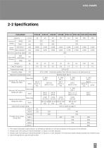
1: The instant allowable surge pressure as defined by DIN24312. Life and durability of the pump will be affected. *2 : Steady state inlet pressure should be greater or equal to 0.9 bar absolute. *3 : Steady state inlet pressure should be greater or equal to 1.3 bar absolute. The maximum boost pressure should not exceed 10 bar. *4 : SAE E through drive uses the SAE D shaft.
Open the catalog to page 9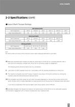
The shaft surface will have a finite life due to wear unless adequate lubrication is provided. #1 Maximum allowable shaft torques are based on achieving an infinite life for a coupling assembly that is lubricated and completely clamped and utilises the full spline/key length as engagement. The following points therefore need to be fully considered:- i) Lubrication of shaft couplings should be in accordance with the coupling manufacturers instructions. ii) The maximum allowable input shaft torque is based on ensuring an infinite life condition by limiting the resultant combined shaft bending and...
Open the catalog to page 10
Pressure at which life and durability will not be affected. The instant allowable surge pressure as defined by BS ISO 2944:2000. Life and durability however will be shortened. Values are valid for an absolute suction pressure of 0.9 bar. If the flow is reduced and the inlet pressure is increased the speed may also be increased. Values stated are the absolute maximum permitted speed for which an increased inlet pressure will be required. Approximate dry weights, dependant on exact pump type. Mineral anti wear hydraulic fluid - for other fluid types please consult KPM UK. If viscosity is in range...
Open the catalog to page 11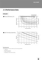
2-3 Performance DataK3VL28♦ Pump Efficiency (%) ♦ Self Priming Capability inlet pressure (bar) Volumetric efficiency(%) Performance Note: All performance curves are based on the following conditions: • Atmospheric inlet condition (0 bar)
Open the catalog to page 12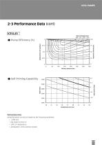
2-3 Performance Data (cont) K3VL45 ♦ Pump Efficiency (%) ♦ Self Priming Capability Performance Note: All performance curves are based on the following conditions: • Atmospheric inlet condition (0 bar)
Open the catalog to page 13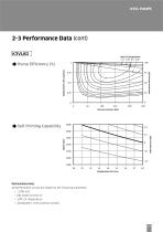
2-3 Performance Data (cont)K3VL60♦ Pump Efficiency (%) Performance Note: All performance curves are based on the following conditions: • Atmospheric inlet condition (0 bar)
Open the catalog to page 14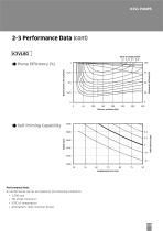
2-3 Performance Data (cont)K3VL80♦ Pump Efficiency (%) Performance Note: All performance curves are based on the following conditions: • Atmospheric inlet condition (0 bar)
Open the catalog to page 15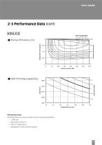
2-3 Performance Data (cont)K3VL112♦ Pump Efficiency (%) Performance Note: All performance curves are based on the following conditions: • Atmospheric inlet condition (0 bar)
Open the catalog to page 16
2-3 Performance Data (cont)K3VL140♦ Pump Efficiency (%) Performance Note: All performance curves are based on the following conditions: • Atmospheric inlet condition (0 bar)
Open the catalog to page 17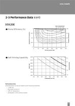
2-3 Performance Data (cont)K3VL200♦ Pump Efficiency (%) Performance Note: All performance curves are based on the following conditions: • Atmospheric inlet condition (0 bar)
Open the catalog to page 18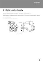
No axial shaft loading possible, radial loading is achievable but in specific orientation:- Radial shaft loading can be allowed provided that its orientation is such that the front bearing takes the additional load (See diagram below). Note: In this case bearing life will be reduced.
Open the catalog to page 19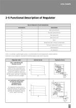
2-5 Functional Description of Regulator Key to Hydraulic Circuit Annotations Regulator Code Control Curves Hydraulic Circuit L0/L1 Load Sense and Pressure Cut-off Pump displacement is controlled to match the flow requirement as a function of the system differential pressure (load pressure vs delivery pressure). In addition, there is a pressure cut off function incorporated into the control. With the LI option,the bleed-off orifice R4 is plugged. LN Load Sense and Pressure Cut-off with Integrated Unloading Valve (Normally Closed) An integrated unloading valve is sandwiched between the Load Sense...
Open the catalog to page 20All Taon Hydraulik Komponenter ApS catalogs and technical brochures
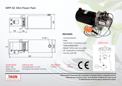 MPP-50
1 Page
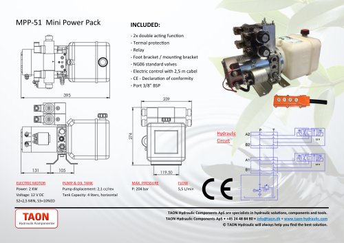 MPP-51
1 Page
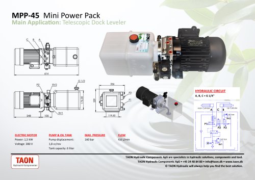 MPP-45
1 Page
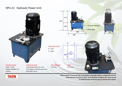 HPU-21
1 Page
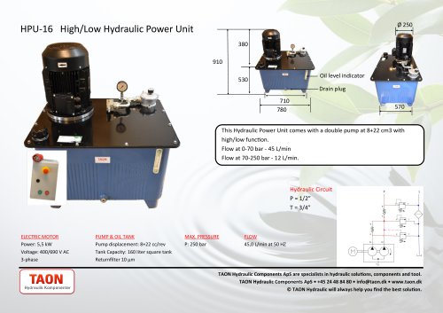 HPU-16
1 Page
 HPU-17
1 Page
 HPU-24
1 Page
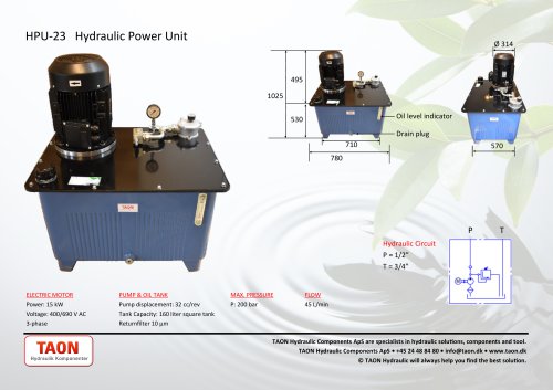 HPU-23
1 Page
 HPU-25
1 Page
 HPU-22
1 Page
 DP22-05
1 Page
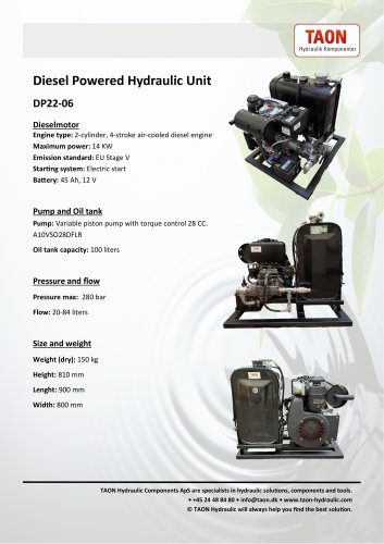 DP22-06
1 Page
 Enerpac RCH-SERIES
3 Pages
 Gear Pump Gr. 1
1 Page
 Gear Pump Gr. 2
1 Page
 Gear Pump Gr. 3
1 Page
 Bent axis piston pumps
8 Pages
 Gr.1 - gearpump
1 Page
 Gr. 2 - Gearpump
1 Page
 Gr.3 - Gearpump
1 Page
 High pressure handpump
1 Page
 VTM Vane pump
4 Pages
 X006
X0061 Page
 X007
X0071 Page
 X066
X0661 Page
 EPA-10521
1 Page
 MR-03-B-3-50
1 Page
 ESH series
1 Page
 PV series
8 Pages
 ED
ED1 Page
 ES Series
1 Page
 K77
K772 Pages
 D-40to100
6 Pages
 ESS
ESS1 Page
 SG
SG5 Pages
 KLV55B
1 Page
 GM10
GM1013 Pages
 HY01001
1 Page
 KK105-4-1284
3 Pages
 NG series 2
3 Pages
 NG series 1
3 Pages
 SP20
SP202 Pages
 F37-M2
1 Page
 EV-23
EV-231 Page
 BD1205
1 Page
 VT127-5-1850
1 Page
 VT76-2-600H
1 Page
 VT76-3-700
1 Page
 45L-GM08-3
13 Pages
 45L-GM
13 Pages
 PMD 6-12-25-45
2 Pages
 VTM42-60-50-20
5 Pages
 VTM42-40-40-20
4 Pages
 VTM42-20-20-20
4 Pages
 V10-1P6P-1C-20R
4 Pages
 EPC-001
1 Page
 PPSE15by-B
1 Page
 GLAPN16
1 Page
 PM6BYB-S
2 Pages
 PP08-25
5 Pages
 DP19-02
1 Page
 MPP-08
1 Page
 HPU-29
1 Page
 BP5.5-01
1 Page
 DP10-01
1 Page
 DP10-03
1 Page
 HPU-06
1 Page
 MPP-43
1 Page
 MPP-48
1 Page
 DP19-01
1 Page
 BP13-01
1 Page
 BP27-01
1 Page
 MM/MS sheet
9 Pages
 Variable piston pump
17 Pages
 Vane pump - double pump
11 Pages
 Signle acting hand pumps
1 Page
 Hydraulic footpump GLAPN
1 Page
 Gr2 - Gearpump
9 Pages
 Double acting hand pump
1 Page
 RW Hydraulic Orbit Motor
7 Pages
 MVW Hydraulic Orbit Motor
5 Pages
 MV Hydraulic Orbit Motor
5 Pages
 MT Hydraulic Orbit Motor
1 Page
 MSW Hydraulic Orbit Motor
8 Pages
 MSS Hydraulic Orbit Motor
7 Pages
 MS Hydraulic Orbit Motor
8 Pages
 MR Hydraulic Orbit Motor
8 Pages
 MH Hydraulic Orbit Motor
7 Pages
 Gr. 2 GEAR MOTORS
2 Pages
 Hydraulic Motors VMF
6 Pages
 TG Hydraulic Torque Motor
8 Pages
 MPP-13
1 Page
 MPP-12
1 Page
 MPP-04
1 Page
 MPP-27
1 Page
 MPP-20
1 Page
 MPP-07
1 Page
 MPP-32
1 Page
 MPP-25
1 Page
 MPP-03
1 Page
 MPP-18
1 Page
 MPP-33
1 Page
 MPP-31
1 Page
 MPP-29
1 Page
 MPP-30
1 Page
 MPP-23
1 Page
 MPP-34
1 Page
 MPP-17
1 Page
 MPP-15
1 Page
 MPP-16
1 Page
 MPP-47
1 Page
 MPP-46 Mini Power Pack
1 Page