- Catalogs
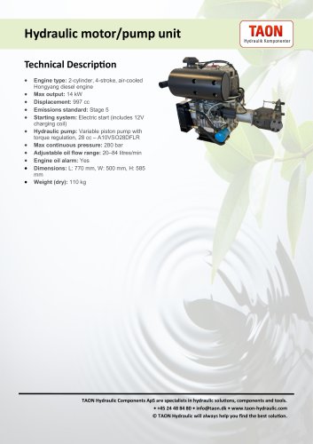
- Taon Hydraulik Komponenter ApS
- 4/2- and 4/3-way proportional directional valves (WRA/WRAE)
4/2- and 4/3-way proportional directional valves (WRA/WRAE)
1 /16Pages
4/2- and 4/3-way proportional directional valves (WRA/WRAE)
1 /16Pages
Catalog excerpts

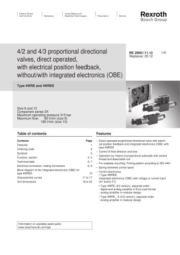
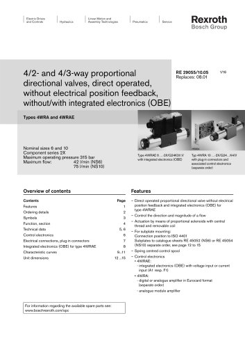
Electric Drives Linear Motion and and Controls I Hydraulics I Assembly Technologies RexrothBosch Group 4/2- and 4/3-way proportional directional valves, direct operated, without electrical position feedback, without/with integrated electronics (OBE) Types 4WRA and 4WRAE Nominal sizes 6 and 10 Component series 2X Maximum operating pressure Maximum flow: 42 Type 4WRAE 6 ...-2X/G24K31/.V Typ 4WRA 10 ...-2X/G24...K4/V with integrated electronics (OBE) with plug-in connectors and associated control electronics (separate order) Overview of contents Features Contents Page Electrical connections, plug-in connectors 7 Integrated electronics (OBE) for type 4WRAE 8 - Direct operated proportional directional valve without electrical position feedback and integrated electronics (OBE) for - Control the direction and magnitude of a flow - Actuation by means of proportional solenoids with central thread and removable coil Subplates to catalogue sheets RE 45052 (NS6) or RE 45054 (NS10) separate order, see page 12 to 15 - Spring centred control spool - Control electronics - integrated electronics (OBE) with voltage input or current input (A1 resp. F1) - digital or analogue amplifier in Eurocard format (separate order) - analogue module amplifier For information regarding the available spare parts see: www.boschrexroth .com/spc
Open the catalog to page 1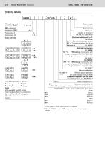
Bosch Rexroth AG | Hydraulics Without integrated With integrated Spool symbols Nominal size 6 Nominal size 10 With spool symbols E1- and W1-: With spools W and WA, in the neutral position, there is a connection from A to T and B to T with approx. 3 % of the relevant nominal crosssection. Further details in clear text Seal material A1 = Command value input ± 10 V F1 = Command value input 4 to 20 mA No code = For 4WRA K4 2) = Without plug-in connector, with component plug to DIN EN 175301-803 plug-in connector - separate order, see page 7 K31 2) = Without plug-in connector, with component plug...
Open the catalog to page 2
Hydraulics Bosch Rexroth AG Symbols Without integrated electronics With integrated electronics (OBE)
Open the catalog to page 3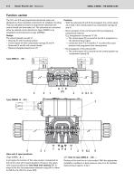
Function, section The 4/2- and 4/3-way proportioanl directional valves are designed as direct operated components for subplate mounting. They are actuated by means of proportional solenoids with central thread and removable coil. The solenoids are controlled either by external control electronics (type 4WRA) or by integrated control electronics (type 4WRAE). Design: The valves basically consist of: – Housing (1) with mounting surface – Control spool (2) with compression springs (3 and 4) – Solenoids (5 and 6) with central thread – Optional integrated electronics (7) Function: – With the solenoids...
Open the catalog to page 4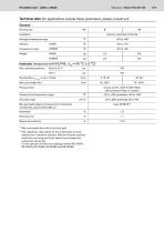
Hydraulics | Bosch Rexroth AG Technical data (for applications outside these parameters, please consult us!) Max. permissible flow with a dual flow path The cleanliness class stated for the components must be adhered too in hydraulic systems. Effective filtration prevents faults from occurring and at the same time increases the component service life. For the selection of filters see catalogue sheets RE 50070, RE 50076, RE 50081, RE 50086 and RE 50088.
Open the catalog to page 5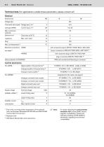
Bosch Rexroth AG | Hydraulics Technical data (for applications outside these parameters, please consult us!) \0T Note: For details regarding the environmental simulation test covering EMC (electromagnetic compatibility), climate and mechanical loading see RE 29055-U (declaration regarding environmental compatibility). Due to the occurring surface temperature of the solenoid coils, the European Standards DIN EN 563 and DIN EN 982 must be taken into account! Separate order With Bosch Rexroth AG control electronics
Open the catalog to page 6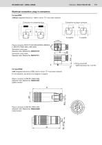
Hydraulics Bosch Rexroth AG Electrical connection, plug-in connectors For type WRA (without integrated electronics – not for version "J" = sea water resistant) Connection on component plug Connection on plug-in connector Plug-in connector CECC 75 301-803-A002FA-H3D08-G to DIN EN 175301-803 or ISO 4400 Solenoid a, colour grey Separate order: Material No. R901017010 Solenoid b, colour black Separate order: Material No. R901017011 1 Fixing screws M3 Tightening torque MA = 0.5 Nm For type WRAE (with integrated electronics (OBE) and for version "J" = sea water resistant) For pin allocation, see block...
Open the catalog to page 7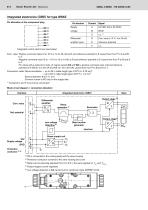
Bosch Rexroth AG | Hydraulics Integrated electronics (OBE) for type WRAE Pin allocation of the component plug Integrated control electronics (see below) Com. value: Positive command value (0 to 10 V or 12 to 20 mA) at D and reference potential to E causes flow from P to A and B to T. Negative command value (0 to - 10 V or 12 to 4 mA) at D and reference potential to E causes flow from P to B and A to T. For valves with a solenoid on side „A“ (spool variants EA and WA) a positive command value at D and reference potential to E (NS 6: 4 to 20 mA and NS 10: 12 to 20 mA) causes flow from P to B and...
Open the catalog to page 8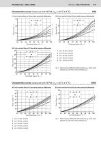
Hydraulics | Bosch Rexroth AG 9/16 Characteristic curves (measured with HLP46, $oil = 40 °C ± 5 °C) Ap = Valve pressure differential (inlet pressure pP minus load pressure pL and minus return pressure pT) Characteristic curves (measured with HLP46, $oil = 40 °C ± 5 °C) Ap = Valve pressure differential (inlet pressure pP minus load pressure pL and minus return pressure pT)
Open the catalog to page 9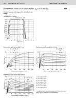
Characteristic curves (measured with HLP46, ϑoil = 40 °C ± 5 °C) Transient functions with stepped form of electrical input signals Types 4WRA and 4WRAE Signal change in % 0 – 100 Performance limit, nominal flow 7 l/min Performance limit, nominal flow 15 l/min 250 100 150 200 Valve pressure differential in bar → 250 100 150 200 Valve pressure differential in bar → Performance limit, nominal flow 30 l/min 50 50 100 250 150 200 Valve pressure differential in bar → 5 Com. value = 80 % 6 Com. value = 90 % 7 Com. value = 100 % If the performance limits are exceeded then flow forces
Open the catalog to page 10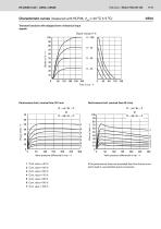
Hydraulics | Bosch Rexroth AG 11 /16 Characteristic curves (measured with HLP46, $oil = 40 °C ± 5 °C)Transient functions with stepped form of electrical input signals Signal change in % Performance limit, nominal flow 60 l/min P ^ A / B ^ T or If the performance limits are exceeded then flow forces occur which lead to uncontrolled spool movements.
Open the catalog to page 11All Taon Hydraulik Komponenter ApS catalogs and technical brochures
 MPP-50
1 Page
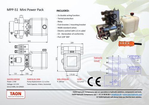 MPP-51
1 Page
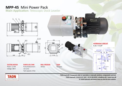 MPP-45
1 Page
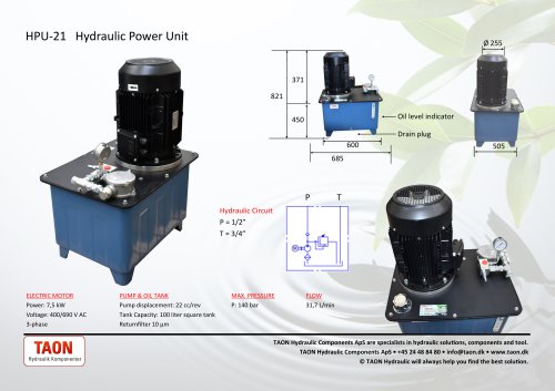 HPU-21
1 Page
 HPU-16
1 Page
 HPU-17
1 Page
 HPU-24
1 Page
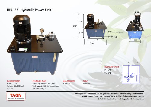 HPU-23
1 Page
 HPU-25
1 Page
 HPU-22
1 Page
 DP22-05
1 Page
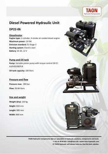 DP22-06
1 Page
 K3VL Kawasaki Piston Pumps
67 Pages
 Enerpac RCH-SERIES
3 Pages
 Gear Pump Gr. 1
1 Page
 Gear Pump Gr. 2
1 Page
 Gear Pump Gr. 3
1 Page
 Bent axis piston pumps
8 Pages
 Gr.1 - gearpump
1 Page
 Gr. 2 - Gearpump
1 Page
 Gr.3 - Gearpump
1 Page
 High pressure handpump
1 Page
 VTM Vane pump
4 Pages
 X006
X0061 Page
 X007
X0071 Page
 X066
X0661 Page
 EPA-10521
1 Page
 MR-03-B-3-50
1 Page
 ESH series
1 Page
 PV series
8 Pages
 ED
ED1 Page
 ES Series
1 Page
 K77
K772 Pages
 D-40to100
6 Pages
 ESS
ESS1 Page
 SG
SG5 Pages
 KLV55B
1 Page
 GM10
GM1013 Pages
 HY01001
1 Page
 KK105-4-1284
3 Pages
 NG series 2
3 Pages
 NG series 1
3 Pages
 SP20
SP202 Pages
 F37-M2
1 Page
 EV-23
EV-231 Page
 BD1205
1 Page
 VT127-5-1850
1 Page
 VT76-2-600H
1 Page
 VT76-3-700
1 Page
 45L-GM08-3
13 Pages
 45L-GM
13 Pages
 PMD 6-12-25-45
2 Pages
 VTM42-60-50-20
5 Pages
 VTM42-40-40-20
4 Pages
 VTM42-20-20-20
4 Pages
 V10-1P6P-1C-20R
4 Pages
 EPC-001
1 Page
 PPSE15by-B
1 Page
 GLAPN16
1 Page
 PM6BYB-S
2 Pages
 PP08-25
5 Pages
 DP19-02
1 Page
 MPP-08
1 Page
 HPU-29
1 Page
 BP5.5-01
1 Page
 DP10-01
1 Page
 DP10-03
1 Page
 HPU-06
1 Page
 MPP-43
1 Page
 MPP-48
1 Page
 DP19-01
1 Page
 BP13-01
1 Page
 BP27-01
1 Page
 MM/MS sheet
9 Pages
 Variable piston pump
17 Pages
 Vane pump - double pump
11 Pages
 Signle acting hand pumps
1 Page
 Hydraulic footpump GLAPN
1 Page
 Gr2 - Gearpump
9 Pages
 Double acting hand pump
1 Page
 RW Hydraulic Orbit Motor
7 Pages
 MVW Hydraulic Orbit Motor
5 Pages
 MV Hydraulic Orbit Motor
5 Pages
 MT Hydraulic Orbit Motor
1 Page
 MSW Hydraulic Orbit Motor
8 Pages
 MSS Hydraulic Orbit Motor
7 Pages
 MS Hydraulic Orbit Motor
8 Pages
 MR Hydraulic Orbit Motor
8 Pages
 MH Hydraulic Orbit Motor
7 Pages
 Gr. 2 GEAR MOTORS
2 Pages
 Hydraulic Motors VMF
6 Pages
 TG Hydraulic Torque Motor
8 Pages
 MPP-13
1 Page
 MPP-12
1 Page
 MPP-04
1 Page
 MPP-27
1 Page
 MPP-20
1 Page
 MPP-07
1 Page
 MPP-32
1 Page
 MPP-25
1 Page
 MPP-03
1 Page
 MPP-18
1 Page
 MPP-33
1 Page
 MPP-31
1 Page
 MPP-29
1 Page
 MPP-30
1 Page
 MPP-23
1 Page
 MPP-34
1 Page
 MPP-17
1 Page
 MPP-15
1 Page
 MPP-16
1 Page
 MPP-47
1 Page
 MPP-46 Mini Power Pack
1 Page