- Catalogs
- Tamura Corporation
- Power Module Application Note
Power Module Application Note
1 /19Pages

Power Module Application Note
1 /19Pages
Catalog excerpts
EPM Series EPM Series Energy-Saving Power Module Series
Open the catalog to page 1
Application Notes EPM Series Energy-Saving Power Module Series Outline The EPM Energy-Saving Power Module Series is a series of energy-saving switching power modules with built-in switching transformers, control ICs, control circuits and switching elements (FET). Attaching the input noise filter, the input rectifier diode and the output smoothing capacitor externally enables the easy creation of power switching with high-efficiency, low-standby power. Quasi-resonant operations for high efficiency. Operations using both frequency reduction and bursts for generation of low-standby power. Supports...
Open the catalog to page 2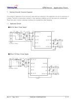
EPM Series Application Notes 1. Selecting Externally Connected Equipment The example of application circuits and parts value which are indicated to this application note aim at assistance of a design. Therefore, external parts variation or user operating conditions are not fully taken into consideration. Please take parts variation, operating conditions into consideration when designing. •With FG (Class I Power Supply) >Without FG (Class II Power Supply) TAMURA CORPORATION
Open the catalog to page 3
Application Notes parts example Output Specifications Output Specifications TAMURA CORPORATION
Open the catalog to page 4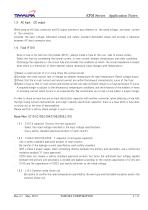
Application Notes When using an AC input connector and DC output connector, pay attention to the rated voltage and rated current of the connector. Consider the input voltage, withstand voltage and safety standard demanded values and provide a clearance between AC input connector pins. Since a fuse is not built into the module (M101), always install a fuse at the Live side to ensure safety. Select the fuse by considering the normal current, in-rush current, ambient temperature, and other conditions. (Discharge the capacitors in the circuit fully and consider the conditions at which the circuit...
Open the catalog to page 5
Application Notes X capacitor discharge resistance (R101 The voltage immediately before cutoff is charged in the X capacitor even when the input line is in cutoff status. With a device at which parts of the same voltage as the X capacitor may be touched, a discharge resistor is necessary according to the capacity of the X capacitor. Example) IEC60950: When the X capacitor capacitance 0.1µF is exceeded; the time constant shall be 1 or less. X capacitor capacitance0.22uF In addition, calculate the X capacitor voltage after t seconds from input line cutoff from the following expression and check...
Open the catalog to page 6
Application Notes When input power is applied, an in-rush current which charges the input smoothing electrolytic capacitor flows. An in-rush current that is too large will cause the power supply voltage to become unstable and may affect the devices which share the power supply. The fuse and rectifying diodes used may also be damaged. When using a power thermistor to suppress the surge current, select it by paying attention to the following: ①Be sure that the temperature is within the operating temperature range of the thermistor. ②Since the characteristic is such that a rated current drop accompanies...
Open the catalog to page 7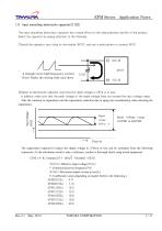
Application Notes Input smoothing electrolytic capacitorC102) The input smoothing electrolytic capacitor has a large effect on the characteristics and life of the product. Select the capacitor by paying attention to the following: ①Install the capacitor very close to the module (M101) and use a wide pattern to connect M101. A triangle wave high frequency current flows. Make the wiring wide and short. Input voltage (VDC) 入力電圧VDC) ②Select an electrolytic capacitor such that the ripple voltage is 25Vp-p or less. In addition, make sure that the peak voltage of the ripple voltage does not exceed...
Open the catalog to page 8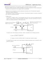
Application Notes ③Calculate the guaranteed life of the electrolytic capacitor and check that there is no problem. Since the life calculation expression is different depending on the capacitor manufacturer and type, requesting life calculation by the manufacturer of the capacitor used is recommended. Generally, life can be calculated by using the temperature and ripple current of the electrolytic capacitor. 1)Electrolytic capacitor temperature The temperature at which the temperature on the body of the electrolytic capacitor is maximum is measured and is made a life calculation parameter. 2)...
Open the catalog to page 9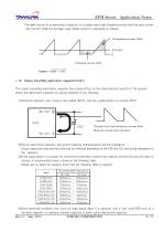
Application Notes The ripple current of an electrolytic capacitor is a triangle wave high frequencycurrent with the input current (DC current) made the average value. Ripple current is calculated as follows: Discharging current (Idis) Output smoothing electrolytic capacitorC201) The output smoothing electrolytic capacitor has a large effect on the characteristics and life of the product. Select the electrolytic capacitor by paying attention to the following: ①Install the capacitor very close to the module (M101) and use a wide pattern to connect M101. Triangle wave high frequency current flows....
Open the catalog to page 10
Application Notes When the overvoltage protection operated, check that the rated voltage of the electrolytic capacitor was not exceeded. The following rated voltage is recommended: ・3.3V output Rated voltage 10Vor more ・5V output Rated voltage 10Vor more ・12V output Rated voltage 25Vor more ・15V output Rated voltage 25Vor more ・24V output Rated voltage 35Vor more Calculate the guaranteed life of the electrolytic capacitor and check that there is no problem. Since the life calculation expression is different depending on the capacitor manufacturer and type, requesting life calculation by the manufacturer...
Open the catalog to page 11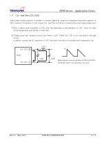
Application Notes Output ripple voltage reduction is possible to a certain degree by using a low impedance electrolytic capacitor at C201. However, the addition of a one-stage LCπ type filter is effective in lowering the output ripple voltage more. ①Since a ripple current equivalent to C201 may flow depending on the impedance of L201, check the ripple current,temperature rise, and life of C202 also. ②Triangle wave high frequency current also flows in L201. Check that L201 is not saturated at the peak current. In addition, consider the DC resistance of L201 and check that there is no problem with...
Open the catalog to page 12All Tamura Corporation catalogs and technical brochures
 S25PxxxD15*
3 Pages
 S26P200D15Y
3 Pages
 S29S1T0D24Z*
4 Pages
 Current Sensors
111 Pages
 Nitrogen Gas Generator
1 Page
 L07PxxxS05
2 Pages
 L07PxxxD15S
2 Pages
 L07PxxxD15
2 Pages
 F03PxxxS05
8 Pages
 F01PxxxS05
7 Pages
 Power Module Handbook
16 Pages
 How to reduce audible_noise
2 Pages
 Application note
19 Pages


- Rail conveyor
- DC power supply
- AC/DC power supply
- Dry transformer
- Horizontal conveyor
- Switching power supply
- Compact power supply
- Encapsulated transformer
- Power transformer
- Current sensor
- Low-voltage transformer
- DC/DC power supply
- AC current sensor
- Ultrasonic transducer
- Cast resin transformer
- High-voltage power supply
- Wire-wound resistor
- Board-mount resistor