Catalog excerpts

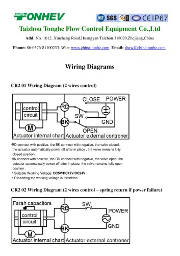
Taizhou Tonghe Flow Control Equipment Co.,Ltd Add: No. 1012, Xincheng Road,Huangyan Taizhou 318020,Zhejiang,China Phone: 86-0576-81100233. Web: www.china-tonhe.com. Email: shaw@china-tonhe.com. Wiring Diagrams CR2 01 Wiring Diagram (2 wires control) ·RD connect with positive, the BK connect with negative, the valve closed, the actuator automatically power off after in place , the valve remains fully closed position. ·BK connect with positive, the RD connect with negative, the valve open, the actuator automatically power off after in place, the valve remains fully open position . Suitable Working Voltage: DC5V/DC12V/DC24V Exceeding the working voltage is forbidden CR2 02 Wiring Diagram (2 wires control – spring return if power failure)
Open the catalog to page 1
· When SW is closed , the valve open. the actuator automatically power off after in place · When SW is open, the valve closed, the actuator automatically power off after in place · Suitable Working Voltage: AC/DC9-24V, AC/DC110V-230V,AC/DC9-35V(with manual override) · Exceeding the working voltage is forbidden · Charging time is at least 60 seconds CR3 01 Wiring Diagram (3 wires control) ·RD & GR connect with positive, BK connect with negative ·When OPEN( RD) & SW connected , the valve open, the actuator automatically power off after in place , valve remains fully open position ·When...
Open the catalog to page 2
CR3 03 Wiring Diagram (3 wires control) ·RD& GR connect with positive, the BK connect with negative。 ·SW CLOSED, the valve OPEN, the actuator automatically power off after in place ·SW OPEN, the valve CLOSED, the actuator automatically power off after in place. Suitable Working Voltage: AC/DC9-35V, AC110V-230V Exceeding the working voltage is forbidden CR4 01 Wiring Diagram (4 wires control) 1. RD & BK are connected to the power, WT & YW are connected to the controlled wiring. 2. When the SW is closed , the valve open 3. When the SW is open , the valve closed Suitable Working...
Open the catalog to page 3
CR5 01 Wiring diagram (with feedback signal) 1. RD connect with positive, the BK connect with negative the valve closed, the actuator automatically power off after in place . 2. BK connect with positive, the RD connect with negativethe valve open, the actuator automatically power off after in place . 4. BL & WT are connect when the valve open fully , YW & WT are connect when the valve closed fully Suitable Working Voltage:DC5V, DC12V/DC24V Exceeding the working voltage is forbidden CR5 02 Wiring diagram (with feedback signal) ·When SW is closed , the valve open. the actuator automatically...
Open the catalog to page 4


