
- Catalogs
- Taiyo Yuden
- Ferrite Power Inductors


- Products
- Catalogs
- News & Trends
- Exhibitions
Ferrite Power Inductors

Ferrite Power Inductors
Reminders:
- Product information is subject to change; verify details before use.
- TAIYO YUDEN is not liable for defects outside specified conditions.
- Contact TAIYO YUDEN for detailed specifications.
- Validate products in actual conditions before shipment.
- Products are for general electronics; contact for critical applications.
- Not for use in aerospace, nuclear, or military applications.
- Ensure protective circuits for high safety or reliability needs.
- Products valid only if purchased through official channels.
- TAIYO YUDEN is not responsible for intellectual property disputes.
- Export may require specific procedures under applicable laws.
Product Specifications:
- Operating Temperature: -25 to +120°C (NRS40/50/60/80: -25 to +125°C).
- Parts Number Structure includes series name, dimensions, packaging, nominal inductance, tolerance, and internal code.
- Standard dimensions and recommended land patterns provided.
Parts Number Details:
- Includes saturation current, temperature rise current, nominal inductance, tolerance, self-resonant frequency, and DC resistance.
- Rated current defined by saturation and temperature rise current values.
Additional Information:
- Refer to the TAIYO YUDEN website for detailed characteristics, reliability, and precautions.
Specifications:
- Reel Sizes: Specific dimensions for types like NRV2010, NRS2012, and NRH2410.
- Top Tape Strength: Peel-off force between 0.1 to 1.3N.
- Operating Temperature: NR series: -25 to +105°C, NS series: -40 to +125°C.
Part Numbering System:
- Series Name: Codes like NR△ and NS△ indicate series and resin specification.
- Dimensions: Codes specify dimensions in millimeters.
- Nominal Inductance: Codes like 3R1 for 3.1μH.
- Inductance Tolerance: ±20% (M) or ±30% (N).
Packaging:
- Minimum Quantity: Standard quantities for tape and reel packaging.
- Tape Material: Embossed tape used for packaging.
- Taping Dimensions: Detailed dimensions for chip cavity and insertion pitch.
Performance Parameters:
- Saturation Current (Idc1): DC current value at which inductance decreases by 30%.
- Temperature Rise Current (Idc2): DC current value at which temperature increases by 40%.
- Rated Current: DC current value satisfying both saturation and temperature rise current values.
Recommendations:
- Check mounting and soldering conditions before use.
- Reflow soldering is recommended.
Additional Information: Refer to the manufacturer's website for detailed product characteristics and reliability information.
Reliability Data: Operating temperature range varies by type, with storage temperature ranges and rated current specifications provided.
Test Methods: Tests include resistance to flexure, insulation resistance, withstanding voltage, adhesion of terminal electrodes, resistance to vibration, solderability, resistance to soldering heat, thermal shock, damp heat, and life tests.
Precautions: Advises on circuit design, PCB design, and automatic placement considerations.
Key Recommendations: Check specifications on the manufacturer's website for detailed product characteristics and reliability information.
- Avoid distortion stress during installation.
- Reflow soldering recommended; verify conditions with the manufacturer.
- Avoid stress until products return to normal temperature post-soldering.
- For lead-free soldering, confirm adhesion and resistance to soldering heat.
- Recommended soldering iron conditions: temperature below 350℃, duration less than 3 seconds.
Cleaning:
- Avoid cleaning with supersonic waves.
Handling:
- Keep products away from magnets and magnetic objects.
- Use appropriate devices for PCB separation.
- Avoid excessive mechanical shocks and pressure on winding parts.
- Do not stack packing boxes.
Storage:
- Control temperature and humidity to maintain solderability and packaging condition.
- Recommended storage conditions: temperature -5 to 40℃, humidity below 70% RH.
- Use products within 6 months of delivery; check solderability if stored longer.
Product Specifications:
- Wire-wound chip power inductors (BR Series) with operating temperature -40 to +105℃.
- Various types and dimensions available, with specific nominal inductance and tolerance codes.
- Recommended land patterns and standard quantities provided.
Performance Characteristics:
- Specifications for saturation current, temperature rise current, self-resonant frequency, and DC resistance.
- Inductance tolerance options include ±10% and ±20%.
For detailed specifications, characteristics graphs, and reliability information, refer to the manufacturer's website.
Packaging Information: Inductors available in paper and embossed tape packaging, with standard quantities specified.
Reliability Data: Outlines reliability tests for BR-series inductors, including operating and storage temperature ranges, rated current, inductance, DC resistance, self-resonance frequency, temperature characteristics, and various mechanical and environmental tests.
Precautions and Handling: Guidelines for circuit design, PCB design, automatic placement, soldering, cleaning, and handling.
- Characteristics may vary with magnetic influence.
- Avoid bending or twisting stress on products.
- Mechanical shock and improper handling can damage products.
- Excessive physical shock and stress can alter electrical characteristics.
- Stacking packing boxes can lead to product and tape breakage.
Storage Conditions:
- Store packing boxes at temperatures between 0 to 40°C and humidity below 70%.
- Recommended storage temperature is below 30°C.
- Solder products within six months of shipment or check solderability before use.
- High temperature or humidity can degrade solderability and tape quality.
Product Specifications:
- Wire-wound chip power inductors (CB Series) operate between -40 to +105°C.
- Part numbers include series name, characteristics, dimensions, packaging, nominal inductance, inductance tolerance, special code, and internal code.
- Dimensions range from 1608 (1.6x0.8 mm) to 3225 (3.2x2.5 mm).
- Packaging is typically taping.
- Inductance tolerance options are ±10% (K) and ±20% (M).
Standard External Dimensions and Quantities:
- Recommended land patterns for surface mounting are provided.
- Standard quantities vary by type and packaging method.
Electrical Characteristics:
- Saturation current (Idc1) and temperature rise current (Idc2) values are specified for each type.
- Inductance values range from 1.0 μH to 1000 μH with varying tolerances.
- Self-resonant frequency and DC resistance are provided for each part number.
Packaging Details:
- Minimum quantities and tape materials are specified for different types.
- Taping dimensions for embossed and card board carrier tapes are detailed.
Additional Information:
- The catalog provides typical specifications; detailed specifications should be checked on the website.
- For further product details, including characteristics graphs and reliability information, visit the manufacturer's website.
Specifications:
- Operating Temperature Range: -40 to +105°C for LB series and -40 to +85°C for CB series.
- Storage Temperature Range: -40 to +85°C for both series.
- Rated Current and Inductance: Values within specified tolerances, measured using LCR meters.
- DC Resistance and Self-Resonant Frequency: Measured with DC Ohmmeters and impedance analyzers.
Reliability Tests:
- Temperature Characteristics: Inductance changes within specified percentages.
- Resistance to Flexure and Body Strength: No damage under specified mechanical stress conditions.
- Adhesion and Vibration Resistance: No abnormalities under specified test conditions.
- Solderability and Resistance to Soldering: At least 90% coverage of terminal electrodes; specific reflow soldering conditions recommended.
- Thermal Shock and Damp Heat Life Tests: Inductance changes within specified limits; no significant appearance changes.
Precautions:
- Circuit Design: Products are for general electronic equipment, not for mission-critical systems.
- PCB Design: Recommended land patterns and reflow soldering conditions provided.
- Handling and Storage: Avoid magnetic fields and mechanical shocks; store under controlled temperature and humidity.
Product Identification: Includes details on series names, dimensions, thickness, nominal inductance, tolerance, packaging, and internal codes for multilayer chip power inductors.
- Operating Temperature Range: Varies across different series, with most ranging from -55°C to +125°C.
- Storage Temperature Range: Generally aligns with operating temperature limits.
- Rated Current: Defined by temperature increase or decrease in internal inductance value under DC bias.
- Impedance: Values specified for each series, with measurement methods detailed.
- Inductance: Values provided for certain series, with measurement frequencies and equipment specified.
- Q Factor: Minimum Q values specified for certain series.
- DC Resistance: Maximum values provided for each series.
- Self Resonance Frequency (SRF): Minimum SRF values specified for certain series.
- Temperature Characteristic: Inductance change within ±10% specified for certain series.
- Resistance to Flexure of Substrate: No mechanical damage specified for all series.
Solderability: For BK and CK series, at least 75% of the terminal electrode must be covered by new solder.
Resistance to Soldering: Inductors must show no significant abnormalities, with impedance changes within specified limits.
Thermal Shock: Inductors should exhibit no significant abnormalities, with impedance or inductance changes within specified limits.
Damp Heat (Steady State): Inductors must maintain appearance and impedance within specified limits.
Loading under Damp Heat: Inductors must show no mechanical damage and maintain specified inductance and Q changes.
Loading at High Temperature: Inductors are tested at high temperatures with rated current.
Precautions on Use: Emphasizes verifying operating environments and electrical ratings.
Technical Considerations: Provides recommended land dimensions for wave and reflow soldering.
Recommended Land Dimensions for Reflow-Soldering: Lists recommended land dimensions for different component sizes.
Solder Application Guidelines: Examples of good and bad solder applications provided.
Automatic Placement Considerations: Precautions include adjusting the mounting machine to avoid excessive impact loads.
Soldering Precautions: Outlines selection of flux and soldering conditions.
Cleaning and Post-Cleaning Processes: Guidelines for cleaning conditions provided.
Handling and Storage Precautions: Handling precautions include avoiding mechanical shocks and controlling temperature and humidity.
Catalog excerpts
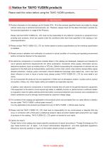
Notice for TAIYO YUDEN products Please read this notice before using the TAIYO YUDEN products. REMINDERS Product information in this catalog is as of October 2014. All of the contents specied herein are subject to change without notice due to technical improvements, etc. Therefore, please check for the latest information carefully before practical application or usage of the Products. Please note that TAIYO YUDEN CO., LTD. shall not be responsible for any defects in products or equipment incorporating such products, which are caused under the conditions other than those specied in this catalog or individual specication. Please contact TAIYO YUDEN CO., LTD. for further details of product specications as the individual specication is available. Please conduct validation and verication of products in actual condition of mounting and operating environment before commercial shipment of the equipment. All electronic components or functional modules listed in this catalog are developed, designed and intended for use in general electronics equipment.(for AV, office automation, household, office supply, information service, telecommunications, (such as mobile phone or PC) etc.). Before incorporating the components or devices into any equipment in the eld such as transportation,( automotive control, train control, ship control), transportation signal, disaster prevention, medical, public information network (telephone exchange, base station) etc. which may have direct inuence to harm or injure a human body, please contact TAIYO YUDEN CO., LTD. for more detail in advance. Do not incorporate the products into any equipment in elds such as aerospace, aviation, nuclear control, submarine system, military, etc. where higher safety and reliability are especially required. In addition, even electronic components or functional modules that are used for the general electronic equipment, if the equipment or the electric circuit require high safety or reliability function or performances, a sufcient reliability evaluation check for safety shall be performed before commercial shipment and moreover, due consideration to install a protective circuit is strongly recommended at customer's design stage. The contents of this catalog are applicable to the products which are purchased from our sales ofces or distributors (so called TAIYO YUDEN s ofcial sales channel ). It is only applicable to the products purchased from any of TAIYO YUDEN s ofcial sales channel. Please note that TAIYO YUDEN CO., LTD. shall have no responsibility for any controversies or disputes that may occur in connection with a third party's intellectual property rights and other related rights arising from your usage of products in this catalog. TAIYO YUDEN CO., LTD. grants no license for such rights. Caution for export Certain items in this catalog may require specic procedures for export according to Foreign Exchange and Foreign Trade Control Law of Japan, U.S. Export Administration Regulations , and other applicable regulations. Should you have any question or inquiry on this matter, please contact our sales staff.
Open the catalog to page 1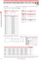
SMD POWER INDUCTORS(NR SERIES/NR SERIES H TYPE/S TYPE/V TYPE) SMD POWER INDUCTORS NR SERIES/NR SERIES H TYPE/S TYPE/V TYPE ■PARTS NUMBER INDUCTORS POWER INDUCTORS *Operating Temp. : -25+120℃ (NRS40/50/60/80 : -25+125℃) Including self-generated heat ①Series name Code NR△ NRH NRS NRV △Blank space Series name Coating resin specification Packaging Taping ④Nominal inductance Code example 2R2 100 101 ※RDecimal point ⑤Inductance tolerance Code M N ⑥Internal code ■STANDARD EXTERNAL DIMENSIONS / STANDARD QUANTITY Recommended Land Patterns Type B ▶ This catalog contains the typical specification only due...
Open the catalog to page 2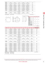
Recommended Land Patterns Type B Unitmm Type Standard quantity [pcs] Taping INDUCTORS POWER INDUCTORS ▶ This catalog contains the typical specification only due to the limitation of space. When you consider the purchase of our products, please check our specification. For details of each product (characteristics graph, reliability information, precautions for use, and so on), see our Web site (http://www.ty-top.com/) .
Open the catalog to page 3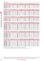
■PARTS NUMBER ●NRS2012 Shielded type Parts number NRS2012T NRS2012T NRS2012T NRS2012T NRS2012T Inductance tolerance Self-resonant frequency MHmin. RoHS RoHS RoHS RoHS RoHS Inductance tolerance Self-resonant frequency MHmin. RoHS RoHS RoHS RoHS RoHS RoHS RoHS Inductance tolerance Self-resonant frequency MHmin. RoHS RoHS RoHS RoHS RoHS Inductance tolerance Self-resonant frequency MHmin. RoHS RoHS RoHS RoHS RoHS RoHS RoHS RoHS RoHS RoHS Inductance tolerance Self-resonant frequency MHmin. RoHS RoHS RoHS RoHS RoHS RoHS RoHS RoHS Inductance tolerance Self-resonant frequency MHmin. RoHS RoHS RoHS RoHS...
Open the catalog to page 4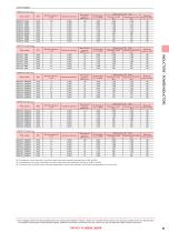
Inductance tolerance Self-resonant frequency MHmin. RoHS RoHS RoHS RoHS RoHS RoHS RoHS RoHS RoHS RoHS Inductance tolerance Self-resonant frequency MHmin. RoHS RoHS RoHS RoHS RoHS RoHS RoHS Inductance tolerance Self-resonant frequency MHmin. RoHS RoHS RoHS RoHS RoHS RoHS RoHS RoHS Inductance tolerance Self-resonant frequency MHmin. RoHS RoHS RoHS RoHS RoHS RoHS RoHS RoHS Inductance tolerance Self-resonant frequency MHmin. RoHS RoHS RoHS RoHS RoHS RoHS RoHS RoHS INDUCTORS POWER INDUCTORS ※ The saturation current value (Idc1) is the DC current value having inductance decrease down to 30%. (at 20℃)...
Open the catalog to page 5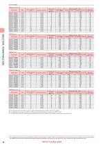
INDUCTORS POWER INDUCTORS Inductance tolerance Self-resonant frequency MHmin. RoHS RoHS RoHS RoHS RoHS RoHS RoHS RoHS RoHS RoHS RoHS RoHS RoHS RoHS Inductance tolerance Self-resonant frequency MHmin. RoHS RoHS RoHS RoHS RoHS RoHS RoHS RoHS Inductance tolerance Self-resonant frequency MHmin. RoHS RoHS RoHS RoHS RoHS RoHS RoHS RoHS Inductance tolerance Self-resonant frequency MHmin. RoHS RoHS RoHS RoHS RoHS RoHS RoHS RoHS RoHS Inductance tolerance Self-resonant frequency MHmin. RoHS RoHS RoHS RoHS RoHS RoHS RoHS RoHS RoHS RoHS ※ The saturation current value (Idc1) is the DC current value having...
Open the catalog to page 6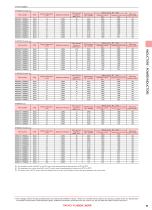
Inductance tolerance Self-resonant frequency MHmin. RoHS RoHS RoHS RoHS RoHS RoHS RoHS RoHS RoHS RoHS Inductance tolerance Self-resonant frequency MHmin. RoHS RoHS RoHS RoHS RoHS RoHS RoHS RoHS RoHS RoHS RoHS Inductance tolerance Self-resonant frequency MHmin. RoHS RoHS RoHS RoHS RoHS RoHS RoHS RoHS RoHS RoHS Inductance tolerance Self-resonant frequency MHmin. RoHS RoHS RoHS RoHS RoHS RoHS RoHS Inductance tolerance Self-resonant frequency MHmin. RoHS RoHS RoHS RoHS RoHS RoHS RoHS RoHS RoHS RoHS RoHS RoHS RoHS RoHS INDUCTORS POWER INDUCTORS ※ The saturation current value (Idc1) is the DC current...
Open the catalog to page 7All Taiyo Yuden catalogs and technical brochures
 HV-6V221MF61Q-R2
2 Pages
 JMK063BJ474MP-F
3 Pages
 JMK063BJ474KP-F
3 Pages
 JMK063ABJ105MP-F
3 Pages
 JMK063ABJ105KP-F
3 Pages
 PMK063EBJ475MP-F
3 Pages
 Common Mode Choke Coils
52 Pages
 Axial Leaded Ceramic Capacitors
26 Pages
 Metal Power Inductors (MCOILTM)
32 Pages
 Multilayer Ceramic Capacitors
49 Pages
 Filter/Coil/Transformer
33 Pages
 Multilayer Chip Varistors
9 Pages
 BD-R
BD-R4 Pages
 DVD-R/DVD+R/DVD-R DL
5 Pages
 Ring Varistors
6 Pages
 Cylinder type PAS Capacitor
4 Pages
 Coin type PAS Capacitor
7 Pages
 Chip Antenna
8 Pages
 Ferrite Cores
7 Pages
 Wound Torroids and Beads
33 Pages
 Axial Leaded Ceramic Capacitors
21 Pages
 Radial Leaded Inductors
15 Pages
 High Current Leaded Inductors
13 Pages
 Leaded Ferrite Beads Inductors
13 Pages
 Axial Leaded Inductors
30 Pages
 MULTILAYER CHIP INDUCTORS
19 Pages
 Balun Transformers
7 Pages
 Wound Chip Inductors LB series
13 Pages
 SMD Inductors Low Profile Type
14 Pages
 WOUND CHIP POWER INDUCTORS
9 Pages
 Wound Inductors (chip/SMD)
56 Pages
 Wireless Module
7 Pages
 Ferrite Chip Beads
47 Pages
 Leaded Inductors
29 Pages
 Multilayer Chip Inductors
33 Pages
 Axial Leaded Ceramic Capacitors
21 Pages
 Multilayer Ceramic Capacitors
45 Pages
 CCFL Inverter(KLS-170A-RH)
2 Pages
 CCFL Inverter(KLS-150A-RH)
2 Pages
 CCFL Inverter(KBI-B02D-RH)
2 Pages
 CCFL Invertor(LS6D0812A-RH)
2 Pages
 CCFL Invertor(LS530-RH)
2 Pages
 CCFL Invertor(LS655-RH)
2 Pages
 CCFL Inverter(LS720A-RH)
2 Pages
 CCFL Inverter(LS700-RH)
2 Pages
 Wireless Module
12 Pages
 CCFL Inverter(SIPF-200A-RH)
2 Pages
 CCFL Inverter(SIPF-150-RH)
2 Pages
 CCFL Inverter(LS460-RH)
2 Pages
 CCFL Inverter(LS380-RH)
2 Pages


![Radial Leaded Inductors[LHL] LHL08TB1R0N](https://img.directindustry.com/pdf/repository_di/20329/radial-leaded-inductors-lhl-lhl08tb1r0n-668548_1mg.jpg)




Archived catalogs
 CD-R
CD-R4 Pages
- Capacitor
- Electronic filter
- Passive electronic filter
- Ceramic capacitor
- Low-pass electronic filter
- SMD capacitor
- Power capacitor
- RoHS capacitor
- Current capacitor
- Compact antenna
- WLAN antenna
- Voltage capacitor
- Cylindrical capacitor
- Multilayer capacitor
- Switching power supply capacitor
- Frequency inductor
- Band-pass electronic filter
- Chip capacitor
- Electrolytic capacitor
- Resistance capacitor