
- Catalogs
- Taiyo Yuden
- Axial Leaded Ceramic Capacitors


- Products
- Catalogs
- News & Trends
- Exhibitions
Axial Leaded Ceramic Capacitors

Axial Leaded Ceramic Capacitors
Reminders:
- Product information is subject to change; verify the latest details before use.
- Taiyo Yuden is not liable for defects under unspecified conditions.
- Contact Taiyo Yuden for detailed specifications and validate products in actual conditions before shipment.
- Products are for general electronics; for critical applications, consult Taiyo Yuden.
- Not suitable for aerospace, aviation, nuclear, or military applications.
- Ensure high safety and reliability evaluations for equipment requiring such standards.
- Products must be purchased through official sales channels.
- Taiyo Yuden is not responsible for intellectual property disputes from product usage.
- Export may require specific procedures under regulations.
Features of Axial Leaded Ceramic Capacitors:
- Capacitance range: 1pF to 10μF.
- Lower insertion costs compared to radial capacitors.
- Mounting pitch: 5mm to 26mm.
- Class 1 products stabilize frequency and temperature characteristics.
- B and F dielectrics are optimal for bypass capacitors.
Specifications:
- Rated Voltage: 10V to 50V.
- Capacitance Tolerances: ±0.5pF to ±20%.
- Temperature Characteristics: CH, SL, B, F.
- Packaging Options: Ammo, Bulk.
Ordering Information:
- Includes rated voltage, type, dimensions, nominal capacitance, temperature characteristics, and packaging.
Electrical Characteristics:
- Capacitance vs. Temperature Characteristics graphs available.
Packaging:
- Details on packaging types and quantities provided.
- Operating Temperature Range: -25 to +85°C for both Class 1 and Class 2 types.
- Rated Voltage: Class 1 rated at 50VDC, Class 2 ranges from 10VDC to 50VDC.
- Insulation Resistance: Minimum values specified based on capacitance and rated voltage, such as 10000MΩ min for Class 1.
- Capacitance Tolerance: Class 1 has a tolerance of ±0.5pF, while Class 2 varies with characteristics B and F.
- Test involves applying a force of 19.6N for 5 seconds, reaching the specified force within 2 seconds.
- Solder temperature set at 230±5℃ for 2±0.5 seconds.
- At least 75% of the lead surface must be covered with new solder.
- Also known as "voltage proof" under IEC specifications.
- No abnormalities should be observed in appearance or voltage withstand capability.
- Class 1 capacitors have specific capacitance change limits and insulation resistance requirements.
- Class 2 capacitors have different parameters based on their rated voltage and capacitance range.
- Referred to as "rapid change of temperature" under IEC specifications.
- Involves cycling through specified temperature ranges with recovery periods.
- Test conditions include a temperature of 40±2℃ and humidity of 90 to 95% RH for 500 hours.
- Preconditioning and recovery periods specified for both Class 1 and Class 2 capacitors.
- Involves testing under specified humidity and temperature conditions.
- Capacitance change and insulation resistance monitored for compliance with specified limits.
1. Voltage Ratings: Capacitors are rated at 25VDC, 35VDC, and 50VDC with specific capacitance change limits and insulation resistance values.
2. Capacitance Change: Varies within ±30.0% depending on the rated voltage and capacitance range.
3. Insulation Resistance: Minimum values specified for different capacitance ranges.
4. tanδ (Dissipation Factor): Maximum values specified for different capacitance ranges.
Test Methods and Conditions:
1. Temperature and Humidity: Tests conducted at 40±2℃ and 90-95% RH.
2. Duration: 500 hours with specific preconditioning and recovery times.
3. High Temperature Loading Test: Conducted at 85±3℃ for 1000 hours with applied voltage conditions.
Precautions:
1. Circuit Design: Ensure operating voltage is below rated values and consider self-generated heat.
2. Operating Environment: Avoid exposure to water, corrosive gases, and extreme conditions.
3. PCB Design: Match hole dimensions to avoid stress on terminals.
4. Soldering: Use appropriate flux and follow recommended soldering conditions to prevent damage.
5. Cleaning: Ensure cleaning methods do not affect capacitor reliability.
6. Handling and Storage: Avoid mechanical shocks and store under controlled temperature and humidity conditions.
Catalog excerpts

1 notice_e-01 Notice for TAIYO YUDEN products@ Please read this notice before using the TAIYO YUDEN products. REMINDERS ¡ Product information in this catalog is as of October 2009. All of the contents specified herein are subject to change without notice due to technical improvements, etc. Therefore, please check for the latest information carefully before practical application or usage of the Products. Please note that Taiyo Yuden Co., Ltd. shall not be responsible for any defects in products or equipment incorporating such products, which are caused under the conditions other than those specified in this catalog or individual specification. ¡ Please contact Taiyo Yuden Co., Ltd. for further details of product specifications as the individual specification is available. ¡ Please conduct validation and verification of products in actual condition of mounting and operating environment before commercial shipment of the equipment. ¡ All electronic components or functional modules listed in this catalog are developed, designed and intended for use in general electronics equipment.(for AV, office automation, household, office supply, information service, telecommunications, (such as mobile phone or PC) etc.). Before incorporating the components or devices into any equipment in the field such as transportation,( automotive control, train control, ship control), transportation signal, disaster prevention, medical, public information network (telephone exchange, base station) etc. which may have direct influence to harm or injure a human body, please contact Taiyo Yuden Co., Ltd. for more detail in advance. Do not incorporate the products into any equipment in fields such as aerospace, aviation, nuclear control, submarine system, military, etc. where higher safety and reliability are especially required. In addition, even electronic components or functional modules that are used for the general electronic equipment, if the equipment or the electric circuit require high safety or reliability function or performances, a sufficient reliability evaluation check for safety shall be performed before commercial shipment and moreover, due consideration to install a protective circuit is strongly recommended at customer's design stage. ¡ The contents of this catalog are applicable to the products which are purchased from our sales offices or distributors (so called “TAIYO YUDEN’s official sales channel”). It is only applicable to the products purchased from any of TAIYO YUDEN’ s official sales channel. ¡ Please note that Taiyo Yuden Co., Ltd. shall have no responsibility for any controversies or disputes that may occur in connection with a third party's intellectual property rights and other related rights arising from your usage of products in this catalog. Taiyo Yuden Co., Ltd. grants no license for such rights. ¡ Caution for export Certain items in this catalog may require specific procedures for export according to “Foreign Exchange and Foreign Trade Control Law” of Japan, “U.S. Export Administration Regulations”, and other applicable regulations. Should you have any question or inquiry on this matter, please contact our sales staff. Should you have any question or inquiry on this matter, please contact our sales staff.
Open the catalog to page 1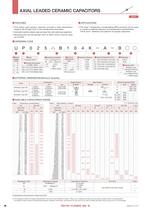
36 1 leaded_c01_e-01 ¡ FEATURES ¡ ORDERING CODE ¡ EXTERNAL DIMENSIONS/Minimum Quantity ¡ AVAILABLE CAPACITANCE RANGE ¡ APPLICATIONS WV 50ViUPj 35ViGPj 25ViTPj 16V iEPj 10ViLPj Temp.char. B F B F B F B F F Type cap. 025 050 075 025 050 050 075 075 075 025 025 050 025 050 050 mpFn mpFF3digitsn 100 101 120 121 150 151 180 181 220 221 270 271 330 331 390 391 470 471 560 561 680 681 820 821 1000 102 1200 122 1500 152 1800 182 2200 222 2700 272 3300 332 3900 392 4700 472 5600 562 6800 682 8200 822 10000 103 12000 123 15000 153 18000 183 22000 223 27000 273 33000 333 39000 393 47000 473 56000 563 68000...
Open the catalog to page 2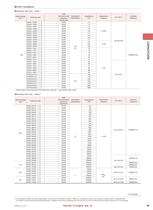
CAPACITORS leaded_c01_e-01 1 37 ¡ PART NUMBERS – This catalog contains the typical specification only due to the limitation of space. When you consider purchase of our products, please check our specification. For details of each product (characteristics graph, reliability information, precautions for use, and so on), see our Web site (http://www.ty-top.com/) or CD catalogs. œMultilayer 025 Type@Class 1 Rated Voltage iDCj Ordering code EHS (Environmental Hazardous Substances) Temperature characteristics Capacitance kpFl Capacitance tolerance Q or tanä Insulation resistance 50V UP025¢010D |› Z...
Open the catalog to page 3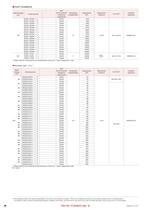
38 1 leaded_c01_e-01 ¡ PART NUMBERS – This catalog contains the typical specification only due to the limitation of space. When you consider purchase of our products, please check our specification. For details of each product (characteristics graph, reliability information, precautions for use, and so on), see our Web site (http://www.ty-top.com/) or CD catalogs. Rated Voltage iDCj Ordering code EHS (Environmental Hazardous Substances) Temperature characteristics Capacitance kpFl Capacitance tolerance Q or tanä Insulation resistance 50V UP050CH220J| › Z RoHS CH 22 ±5% Q†400{20C 10000MÙmin. š...
Open the catalog to page 4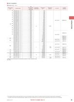
CAPACITORS leaded_c01_e-01 1 39 ¡ PART NUMBERS – This catalog contains the typical specification only due to the limitation of space. When you consider purchase of our products, please check our specification. For details of each product (characteristics graph, reliability information, precautions for use, and so on), see our Web site (http://www.ty-top.com/) or CD catalogs. œMultilayer type@Class 2 Rated Voltage iDCj Ordering code EHS (Environmental Hazardous Substances) Temperature characteristics Capacitance kpFl Capacitance tolerance Q or tanä Insulation resistance 50V š U P 0 5 0 B 1 2 2...
Open the catalog to page 5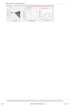
40 1 leaded_c01_e-01 ¡ ELECTRICAL CHARACTERISTICS – This catalog contains the typical specification only due to the limitation of space. When you consider purchase of our products, please check our specification. For details of each product (characteristics graph, reliability information, precautions for use, and so on), see our Web site (http://www.ty-top.com/) or CD catalogs. -6 -7 SL -20 0 20 40 60 80 UP050 F104Z -10 -5 0 5 10 -20 0 20 40 60 80 UP050B103K UP050B104K ¡Capacitance -vs- Temperature Characteristics
Open the catalog to page 6All Taiyo Yuden catalogs and technical brochures
 HV-6V221MF61Q-R2
2 Pages
 JMK063BJ474MP-F
3 Pages
 JMK063BJ474KP-F
3 Pages
 JMK063ABJ105MP-F
3 Pages
 JMK063ABJ105KP-F
3 Pages
 PMK063EBJ475MP-F
3 Pages
 Common Mode Choke Coils
52 Pages
 Ferrite Power Inductors
81 Pages
 Axial Leaded Ceramic Capacitors
26 Pages
 Metal Power Inductors (MCOILTM)
32 Pages
 Multilayer Ceramic Capacitors
49 Pages
 Filter/Coil/Transformer
33 Pages
 Multilayer Chip Varistors
9 Pages
 BD-R
BD-R4 Pages
 DVD-R/DVD+R/DVD-R DL
5 Pages
 Ring Varistors
6 Pages
 Cylinder type PAS Capacitor
4 Pages
 Coin type PAS Capacitor
7 Pages
 Chip Antenna
8 Pages
 Ferrite Cores
7 Pages
 Wound Torroids and Beads
33 Pages
 Axial Leaded Ceramic Capacitors
21 Pages
 Radial Leaded Inductors
15 Pages
 High Current Leaded Inductors
13 Pages
 Leaded Ferrite Beads Inductors
13 Pages
 Axial Leaded Inductors
30 Pages
 MULTILAYER CHIP INDUCTORS
19 Pages
 Balun Transformers
7 Pages
 Wound Chip Inductors LB series
13 Pages
 SMD Inductors Low Profile Type
14 Pages
 WOUND CHIP POWER INDUCTORS
9 Pages
 Wound Inductors (chip/SMD)
56 Pages
 Wireless Module
7 Pages
 Ferrite Chip Beads
47 Pages
 Leaded Inductors
29 Pages
 Multilayer Chip Inductors
33 Pages
 Multilayer Ceramic Capacitors
45 Pages
 CCFL Inverter(KLS-170A-RH)
2 Pages
 CCFL Inverter(KLS-150A-RH)
2 Pages
 CCFL Inverter(KBI-B02D-RH)
2 Pages
 CCFL Invertor(LS6D0812A-RH)
2 Pages
 CCFL Invertor(LS530-RH)
2 Pages
 CCFL Invertor(LS655-RH)
2 Pages
 CCFL Inverter(LS720A-RH)
2 Pages
 CCFL Inverter(LS700-RH)
2 Pages
 Wireless Module
12 Pages
 CCFL Inverter(SIPF-200A-RH)
2 Pages
 CCFL Inverter(SIPF-150-RH)
2 Pages
 CCFL Inverter(LS460-RH)
2 Pages
 CCFL Inverter(LS380-RH)
2 Pages


![Radial Leaded Inductors[LHL] LHL08TB1R0N](https://img.directindustry.com/pdf/repository_di/20329/radial-leaded-inductors-lhl-lhl08tb1r0n-668548_1mg.jpg)




Archived catalogs
 CD-R
CD-R4 Pages
- Electronic filter
- Passive electronic filter
- Low-pass electronic filter
- SMD capacitor
- Power capacitor
- RoHS capacitor
- Current capacitor
- Compact antenna
- WLAN antenna
- Voltage capacitor
- Cylindrical capacitor
- Multilayer capacitor
- Switching power supply capacitor
- Frequency inductor
- Band-pass electronic filter
- Chip capacitor
- Electrolytic capacitor
- Resistance capacitor