- Catalogs
- Taiwan Semiconductor
- TS1431ACX Power Management Ics-Voltage Reference-Voltage Reference
TS1431ACX Power Management Ics-Voltage Reference-Voltage Reference
1 /10Pages

TS1431ACX Power Management Ics-Voltage Reference-Voltage Reference
1 /10Pages
Catalog excerpts
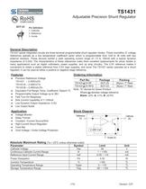
TS1431 Adjustable Precision Shunt Regulator SOT-23 Pin Definition: 1. Cathode 2. Reference 3. Anode General Description TS1431 series integrated circuits are three-terminal programmable shunt regulator diodes. These monolithic IC voltage references operate as a low temperature coefficient zener which is programmable from Vref to 36 volts with two external resistors. These devices exhibit a wide operating current range of 1.0 to 100mA with a typical dynamic impedance of 0.22Ω. The characteristics of these references make them excellent replacements for zener diodes in many applications such as digital voltmeters, power supplies, and op amp circuitry. The 2.5V reference makes it convenient to obtain a stable reference from 5.0V logic supplies, and since The TS1431 series operates as a shunt regulator, it can be used as either a positive or negative stage reference. Ordering Information Precision Reference Voltage TS1431 – 2.495V±2% TS1431A – 2.495V±1% TS1431B – 2.495V±0.5% Equivalent Full Range Temp. Coefficient: 50ppm/ ºC Programmable Output Voltage up to 36V Fast Turn-On Response Sink Current Capability of 1~100mA Low Dynamic Output Impedance: 0.2Ω Low Output Noise TS1431xCX RF SOT-23 3Kpcs / 7” Reel TS1431xCX RFG SOT-23 3Kpcs / 7” Reel Note: “G” denote for Green Product Where xx denotes voltage tolerance Blank: ±2%, A: ±1%, B: ±0.5% Block Diagram Voltage Monitor Delay Timmer Constant –Current Source/Sink High-Current Shunt Regulator Crow Bar Over-Voltage / Under-Voltage Protection Absolute Maximum Rating (Ta = 25oC unless otherwise noted) Parameter Cathode Voltage Continuous Cathode Current Range Reference Input Current Range Power Dissipation Junction Temperature Operating Temperature Range Storage Temperature Range
Open the catalog to page 1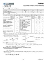
TS1431 Adjustable Precision Shunt Regulator Recommend Operating Condition Parameter Cathode Voltage (Note 1) Continuous Cathode Current Range Recommend Operating Condition Parameter TS1431 TS1431A TS1431B Deviation of reference input voltage Radio of change in Vref to change in cathode Voltage Reference voltage Reference Input current Deviation of reference input current, over temp. Off-state Cathode Current Dynamic Output Impedance Symbol VREF ∆ VREF ∆VREF /∆VKA IREF ∆IREF IKA (off) | ZKA | Test Conditions VKA =VREF, IK =10mA (Figure 1) o Ta=25 C VKA = VREF, IK =10mA (Figure 1) Ta= full range...
Open the catalog to page 2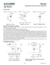
Test Circuits Adjustable Precision Shunt Regulator Input o-AA/V Figure 3: Off-State Current Additional Information - Stability When The TS1431/1431 A/1431 B is used as a shunt regulator, there are two options for selection of CL, are recommended for optional stability: A) No load capacitance across the device, decouple at the load. B) Large capacitance across the device, optional decoupling at the load. The reason for this is that TS1431/1431 A/1431 B exhibits instability with capacitances in the range of 10nF to 1uF (approx.) at light cathode current up to 3mA (typ). The device is less stable...
Open the catalog to page 3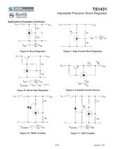
Adjustable Precision Shunt Regulator Applications Examples (Continue) Figure 6: Shunt Regulator Figure 7: High Current Shunt Regulator Figure 8: Series Pass Regulator Figure 9: Constant Current Source Figure 10: TRIAC Crowbar
Open the catalog to page 4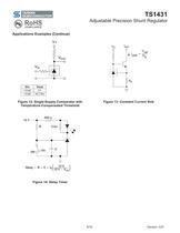
Applications Examples (Continue) Figure 12: Single-Supply Comparator with Temperature-Compensated Threshold Adjustable Precision Shunt Regulator Figure 13: Constant Current Sink Delay= RxCxU^y Figure 14: Delay Timer
Open the catalog to page 5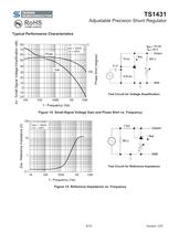
Typical Performance Characteristics Adjustable Precision Shunt Regulator Test Circuit for Voltage Amplification Figure 14: Small-Signal Voltage Gain and Phase Shirt vs. Frequency Test Circuit for Reference Impedance Figure 15: Reference Impedance vs. Frequency
Open the catalog to page 6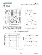
Typical Performance Characteristics (Continue) Adjustable Precision Shunt Regulator The areas under the curves represent conditions that may cause the device to oscillate. For curves B, C, and D, R2 and V+ were adjusted to establish the initial VKA and IKA conditions with Ci_=0. VBATT and Ci_ then were adjusted to determine the ranges of stability. Test Circuit for Curve A Test Circuit for Curve B, C and D Figure 16: Stability Boundary Condition Test Circuit for Pulse Response, lk=1mA Figure 17: Pulse Response
Open the catalog to page 7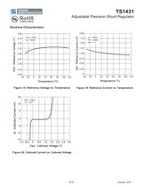
Electrical Characteristics Adjustable Precision Shunt Regulator Figure 20: Cathode Current vs. Cathode Voltage
Open the catalog to page 8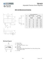
TS1431 Adjustable Precision Shunt Regulator Marking Diagram 1 = Device Code X = Tolerance Code (A = ±1%, B = ±0.5%, C = ±2%,) Y = Year Code M = Month Code (A=Jan, B=Feb, C=Mar, D=Apl, E=May, F=Jun, G=Jul, H=Aug, I=Sep, J=Oct, K=Nov, L=Dec) L = Lot Code
Open the catalog to page 9
TS1431 Adjustable Precision Shunt Regulator Notice Specifications of the products displayed herein are subject to change without notice. TSC or anyone on its behalf, assumes no responsibility or liability for any errors or inaccuracies. Information contained herein is intended to provide a product description only. No license, express or implied, to any intellectual property rights is granted by this document. Except as provided in TSC’s terms and conditions of sale for such products, TSC assumes no liability whatsoever, and disclaims any express or implied warranty, relating to sale and/or use...
Open the catalog to page 10All Taiwan Semiconductor catalogs and technical brochures
 TS1117BCW50
7 Pages
 TS1117BCW33
7 Pages
 TS2937CM33
10 Pages
 TS1935BCX5
8 Pages
 TS2581CS
7 Pages
 TS2596CM5
8 Pages
 TS2596CM533
8 Pages
 TS2596CM550
8 Pages
 TS1431BCX
10 Pages
 TS431ACX-Z
10 Pages
 TS431ARCX-Z
10 Pages
 TS431ARIX-Z
7 Pages
 TS431BCX-Z
10 Pages
 TS431BRIX-Z
7 Pages
 TS432ACT
12 Pages
 TSH181CT
7 Pages
 TSH188CT
8 Pages
 TSH188CX
8 Pages
 TSH190CT
8 Pages
 TSH190CX
8 Pages
 TSC Web Selector Guide
43 Pages
 TS19320CS
9 Pages
 TSM015NA03CR_A1612
6 Pages
 TESD24VS2BT_A1805
5 Pages
 MCR100-3
5 Pages
 1.5KE
1.5KE6 Pages
 ABS2
ABS24 Pages
 ES1G
ES1G4 Pages
 ES1FL
ES1FL4 Pages
 ES1DL
ES1DL4 Pages
 ES1CL
ES1CL4 Pages
 ES1BL
ES1BL4 Pages
 ES1AL
ES1AL4 Pages
 ES0406D1
3 Pages
 PRODUCT SELECTOR GUIDE
27 Pages
 Product Shortform
97 Pages


Archived catalogs
 High Voltage NPN Transistor
6 Pages
 20V Dual N- Channel MOSFET
6 Pages


