- Catalogs
- Syslogic GmbH
- DS_SiliconDriveII-4500
DS_SiliconDriveII-4500
1 /120Pages

DS_SiliconDriveII-4500
1 /120Pages
Catalog excerpts
Data Sheet WD SiliconDrive II ® CF SSD-Cxxx(I)-45xx WD CONFIDENTIAL
Open the catalog to page 1
© 2010 Western Digital Technologies, Inc. All Rights Reserved Information furnished by WD is believed to be accurate and reliable. No license is granted by implication or otherwise under any patent or patent rights of WD. WD reserves the right to change specifications at any time without notice. Western Digital Technologies, Inc., the WD logo, SiliconDrive, PowerArmor, and SiSMART are registered trademarks in the U.S. and other countries; and LifeEST is a trademark of Western Digital Technologies. Other marks may be mentioned herein that belong to other companies. Data reflects products in production...
Open the catalog to page 2
SSD-Cxxx(I)-45xx Data Sheet 1.0 Description and Features DESCRIPTION AND FEATURES 1.1 Overview WD SiliconDrive II technology is engineered exclusively for the high performance, high reliability and multiyear product lifecycle requirements of the embedded and communications market. Typical end-market applications include broadband data and voice networks, military systems, flight system avionics, medical equipment, industrial control systems, video surveillance, storage networking, VoIP, wireless infrastructure, and interactive kiosks. Every WD SiliconDrive II CF is integrated with WD’s patented...
Open the catalog to page 9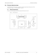
SSD-Cxxx(I)-45xx Data Sheet 2.0 Description and Features PHYSICAL SPECIFICATIONS The WD SiliconDrive II CF products are offered in an industry-standard Type I form factor. See “Part Numbering” on page 117 for details regarding CF capacities. 2.1 Physical Dimensions This section provides diagrams that describe the physical dimensions for the CF. Figure 2-1. Physical Dimensions 2679-771294-A02 RELEASED 12/23/10 (WD CONFIDENTIAL) 10
Open the catalog to page 10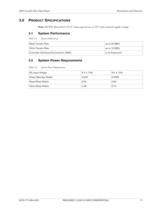
SSD-Cxxx(I)-45xx Data Sheet 3.0 Description and Features PRODUCT SPECIFICATIONS Note: All WD SiliconDrive II CF values quoted are at 25°C and nominal supply voltage. 3.1 System Performance Table 3-1. System Performance Read Transfer Rate up to 34 MB/s Write Transfer Rate up to 19 MB/s Controller Overhead (Command to DRQ) 2 ms (maximum) 3.2 System Power Requirements Table 3-2. System Power Requirements DC Input Voltage 3.3 ± 10% 5.0 ± 10% Sleep (Standby Watts) 0.002 0.0065 Read (Peak Watts) 0.52 0.90 Write (Peak Watts) 0.48 0.74 2679-771294-A02 RELEASED 12/23/10 (WD CONFIDENTIAL) 11
Open the catalog to page 11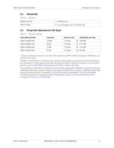
3.4 Projected Operational Life Span Table 3-4. Operational Life Span * There are unlimited read cycles. Service life is determined using WD's LifeEST calculation at 100% duty cycle with 25% write cycles. LifeEST is a comprehensive measurement that considers numerous factors to determine the projected life span of a SiliconDrive. A white paper that describes the benefits of LifeEST and how to calculate it can be found at The actual life of a SiliconDrive is dependent on the customer usage model. SiSMART is a patented technology of WD that enables host systems to monitor actual usage of a SiliconDrive...
Open the catalog to page 12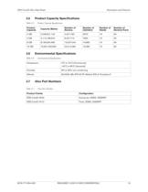
SSD-Cxxx(I)-45xx Data Sheet 3.5 Description and Features Product Capacity Specifications Table 3-5. Product Capacity Specifications Product Capacity Capacity (Bytes) Number of Sectors Number of Cylinders Number of Heads Number of Sectors/Track 2 GB 2,048,901,120 4,001,760 3970 16 63 4 GB 4,110,188,544 8,027,712 7964 16 63 8 GB 8,195,604,480 16,007,040 15,880 16 63 16 GB 16,391,208,960 32,014,080 16,383 16 63 3.6 Environmental Specifications Table 3-6. Environmental Specifications Temperature 0ºC to 70ºC (Commercial) -40ºC to 85ºC (Industrial) Humidity 8% to 95% non-condensing Altitude 80,000ft,...
Open the catalog to page 13
The following table describes the WD SiliconDrive II CF 50-pin IDE connector signals. 1 = These signals are required only for 16-bit access, and not required when installed in 8-bit systems.
Open the catalog to page 14
SSD-Cxxx(I)-45xx Data Sheet 4.2 Description and Features Signal Descriptions Table 4-2. Signal Descriptions Signal Name Pin Type Description A10-A0 8, 10, 11, 12, I 14, 15, 16, 17, 18, 19, 20 A10-A0 (PC Card I/O mode) These address lines along with the -REG signal are used to select the following: • The I/O port address registers within the WD SiliconDrive II CF • The memory-mapped port address registers within the WD SiliconDrive II CF • A byte in the card's information structure and its configuration control and status registers This signal is the same as the PC Card Memory Mode signal. A2-A0...
Open the catalog to page 15
SSD-Cxxx(I)-45xx Data Sheet Table 4-2. Description and Features Signal Descriptions (Continued) Signal Name Pin Type Description -CE1, -CE2 (PC Card memory mode) Card Enable 7, 32 I These input signals are used both to select the card and to indicate to the card whether a byte or a word operation is being performed. • -CE2 always accesses the odd byte of the word. • -CE1 accesses the even byte or the odd byte of the word depending on A0 and -CE2. A multiplexing scheme based on A0, -CE1, and -CE2 allows 8-bit hosts to access all data on D0-D7. See “Attribute Memory Read Operations” on page 39,...
Open the catalog to page 16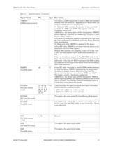
SSD-Cxxx(I)-45xx Data Sheet Table 4-2. Description and Features Signal Descriptions (Continued) Signal Name Pin Type Description -DMARQ (UDMA protocol active) This signal is a DMA request that is used for DMA data transfers between host and device. It is asserted by the device when it is ready to transfer data to or from the host. For Multiword DMA transfers, the direction of data transfer is controlled by -IORD and -IOWR. This signal is used in a handshake manner with -DMACK (i.e., the device waits until the host asserts (-)DMACK before negating (-)DMARQ, and reasserting (-)DMARQ if there is...
Open the catalog to page 17
SSD-Cxxx(I)-45xx Data Sheet Table 4-2. Description and Features Signal Descriptions (Continued) Signal Name Pin Type Description -IORD (PC Card memory mode) 34 I This signal is not used in this mode. -IORD (PC Card I/O mode) This is an I/O read strobe generated by the host. This signal gates I/O data onto the bus from the WD SiliconDrive II CF when the card is configured to use the I/O interface. -IORD (True IDE mode) In true IDE mode, this signal has the same function as the PC Card I/O mode. -HDMARDY (UDMA When UDMA mode DMA read is active in all modes, this signal is asserted by the host to...
Open the catalog to page 18All Syslogic GmbH catalogs and technical brochures
 TFT/PANxxxIS Series
2 Pages
 COMPACT AI Rugged Series
2 Pages
 COMPACT AI Rail Series
2 Pages
 COMPACT-S AI Series
2 Pages
 Industrial PC COMPACT C7
2 Pages
 Industrial Grad CFast 602S
98 Pages
 TFT/HVXxxxPU71 Series (VESA)
2 Pages
 PROTOUCH-8 Series (Build-in)
3 Pages
 Analog I/O Module
2 Pages
 Digital I/O Module
2 Pages
 USB to 422/485 Converter
2 Pages
 Desktop Power Supply
2 Pages
 IPC/WLB-P
2 Pages
 CPN/ANTWLPT-1A
16 Pages
 CPN/ANTGPS-1A
14 Pages
 Embedded PC/COMPACT81 - S
2 Pages
 Railway Computer Compact 8
2 Pages
 Industrial PC/COMPACT C6
2 Pages
 Apacer Industrial CF
20 Pages
 IPC/COMPACT71 - SL
2 Pages
 IPC/COMPACT8 -M
2 Pages
 Cactus SD Card 808 Series
2 Pages
 CompactFlash Series 5
20 Pages
 TFT/HB057RU41
2 Pages
 IPC/COMPACT8 - SL
2 Pages
 IPC/COMPACT41-S
2 Pages
 Embedded PC/COMPACT8 - S
2 Pages
 TFT/HOxxxPU-7
2 Pages
 TFT/HBxxxPU-71
2 Pages
 TFT/HVxxxPU-8
2 Pages
 TFT/PVxxxPU
2 Pages
 IPC/COMPACT8 -RSL
2 Pages
 REC/COMPACT8
2 Pages
 Cactus SD Card 806 Series
2 Pages
 Cactus 910S Series
2 Pages
 Cactus PC-Card 203 Series
2 Pages
 Cactus microSD 803M Series
2 Pages
 TFT/HVxxxPU-71
2 Pages
 Cactus CF 303 Series
2 Pages
 IPC/COMPACT8 -ML
2 Pages
 DS_SIC4
1 Page
 DS_NETSBC71
2 Pages
 DS_NETARM_1AE
2 Pages
 DS_NETIPC_4
2 Pages
 DS_NETIPC_6
2 Pages
 IPC/NETARM-1
2 Pages
 CEM/ATOME6
2 Pages
 Rugged RPC/COMPACT71
2 Pages
 TFT/HOxxxPU7
2 Pages
 TFT/HMIxxxIS6
2 Pages
 SL ? Industrial PC/COMPACT71
2 Pages
 M ? Embedded PC/COMPACT41
2 Pages
 XS ? Box PC/COMPACT6
2 Pages
 S ? Embedded PC/COMPACT41
2 Pages
 MS ? Box PC/COMPACTA1
2 Pages
 IPC/COMPACT71 -RSL
2 Pages
 IPC/WLB-xxxx
2 Pages
 IPC/COMPACT41-M
2 Pages
 IPC/LEANBOX
2 Pages
 TFT/PBxxxPU
2 Pages
 IPC/COMPACT71-ML
2 Pages
 TFT/HVXxxxPU71
2 Pages
 Apacer Industrial SD
18 Pages
 Apacer Industrial CFast
17 Pages
 IPC/SIC4
1 Page
 IPC/DIO32
1 Page
 IPC/NETARM-1AE
2 Pages
 IPC/NETIPC-4
2 Pages
 IPC/NETIPC-6
2 Pages
 TFT/PANxxxIS
2 Pages
 IPC/COMPACT7 -ML
2 Pages
 IPC/COMPACT6 -ML
2 Pages
 Cactus CF 503 Series
2 Pages
 RPC/COMPACT71
2 Pages
 Cactus CFast 900S Series
2 Pages
 Rugged PC/COMPACT71
2 Pages
 IPC/NETSBC71
2 Pages
 CoreExpress - 71
2 Pages
 IPC/COMPACTA1 - XS
2 Pages
 DS_TFT-PBxxxPU_v0.1
2 Pages
 ds_leanbox_v1.1
2 Pages
 DS_M-COMPACT41
2 Pages
 DS_WLB_v0.1
2 Pages
 DS_TFT-HOxxxPU-7_v1.0
2 Pages
 DS_TFT-HVxxxPU-7
2 Pages
 DS_TFT-PANxxxIS_v1.0.
2 Pages
 DS_TFT_HMI150-Family
2 Pages
 DS_TFT_HMI065-Family
2 Pages
 DS_ML-COMPACT7_v2.2
2 Pages
 DS_COMPACT6_ML
2 Pages
 IPC/COMPACT6 -SL
2 Pages
 IPC/COMPACT4 - XS
2 Pages
 IPC/COMPACT6 -XS
2 Pages
 IPC/COMPACTA1 - MS
2 Pages


