
- Catalogs
- Synventive Molding Solutions
- Threaded / Screw Fit 12 E01


Threaded / Screw Fit 12 E01

Threaded / Screw Fit 12 E01
Overview
This technical document provides comprehensive specifications and configuration guidelines for the Series 12 E01 manifold nozzles with screw fit, designed for hot runner injection molding systems. The nozzles feature a 12 mm flow bore diameter and offer multiple interchangeable tip shapes and gating types to suit various plastic materials and processing conditions.
1. Product Classification and Nomenclature
- Series: 12 E01
- Nozzle Size: Flow bore diameter of 12 mm
- Nozzle Style: Manifold nozzle with screw fit
- Version: Basic version with interchangeable screw-in nozzle tips
- Tip Shapes and Gating Types: Includes multiple tip shapes (Y, U, P, K, L) and gating types such as open, open with torpedo, and valve gate.
2. Key Dimensions and Parameters
- Nozzle Length (L): Variable depending on tip shape and length code, ranging approximately from 96 mm to over 600 mm.
- Cut Out Dimensions: Mold plate cut-outs specified for nozzle and connections, including grooves for locking pins to prevent rotation.
- Flow Bore Diameter: Standardized at 12 mm.
- Tip Diameter and Hot Runner Gate Diameter: Varies according to nozzle tip type.
3. Heating and Electrical Specifications
- Externally heated nozzles operating at 230 V AC.
- Heating zones range from 1 to 3, with power ratings between 315 W and 1115 W depending on nozzle length and type.
- Temperature sensing via Fe/CuNi thermocouples compliant with DIN 43710.
4. Applications and Material Compatibility
- Suitable for all common thermoplastics.
- Maximum shot weight per nozzle varies by gating type and material viscosity: up to 1500 g for open gates with low viscosity materials, approximately 500 g for valve gate with low viscosity materials.
5. Nozzle Tip Types and Features
- Open (N): Standard open gate for general applications.
- Open with Torpedo (T): Enhanced flow control with torpedo-shaped tip, suitable for medium to wide process windows.
- Valve Gate (V): Provides precise gating control, recommended for narrow to medium process windows.
6. Design and Installation Considerations
- Locking pin grooves and bores secure the nozzle against rotation.
- Cooling is required around the nozzle tip and on the opposite side to maintain optimal processing temperatures.
- The nozzle tip front must always be positioned against the plastic to ensure proper gating.
- General tolerances and surface finishes comply with DIN ISO 2768-mK standards.
7. Configuration and Selection
- Nozzle length codes correspond to specific length ranges or exact lengths depending on the series.
- Heating zone power ratings vary with nozzle length and configuration.
- Users configure nozzles by selecting series, type, length code, and tip shape based on application requirements.
8. Additional Notes and Recommendations
- Illustrations are schematic and not to scale.
- For detailed design and application guidance, refer to the Synventive Hot Runner Guide.
- Consult Synventive for specific application requirements and confirmation of nozzle configuration.
- Ensure compliance with DIN ISO 2768-mK tolerances for mold plate cut-outs and nozzle installation.
- Verify nozzle tip shape and gating type according to the material’s process window.
9. Technical Specifications and Tolerances
- Groove and bore dimensions for locking pins and mold plate cut-outs are specified (details referenced but not included).
- General tolerances for length, shape, and position follow DIN ISO 2768-mK standards.
- Critical dimensional parameters include total length (L), sub-lengths (L1, L2), height (H), and angles (G, F) with specified radius and tolerance limits.
10. Heater Zones and Power Ratings
- Heater power ratings per zone range from 315 W to 1115 W, increasing with nozzle length.
- Tables correlate length codes with heater power requirements for precise thermal management.
11. Nozzle Types and Versions
- Multiple nozzle types (C, P, T, A, S, V, W) with specific tip shapes and gating mechanisms.
- Valve gate types (V) include tip shapes L, S, W; open with torpedo types (T) include S, W.
- Versions 01 and 02 indicate suitability for different process windows and installation constraints.
12. Installation and Application Notes
- Nozzle tip front must contact plastic material for proper gating.
- Cooling is mandatory around the nozzle tip and opposite side.
- Manifold nozzles use screw fit and gating types vary by application.
- Nomenclature differences exist between older and newer nozzle series due to revisions.
13. Summary of Key Tables
- Tables provide length ranges with corresponding heater power per zone.
- Angular parameters and dimensional tolerances are tabulated for precise specification.
- Cooling and heating power requirements increase with nozzle length.
14. Contact Information
Regional contact details are provided for multiple countries to ensure localized technical and sales support.
Critical Recommendations
- Always verify nozzle tip shape and gating type according to the material’s process window.
- Ensure compliance with DIN ISO 2768-mK tolerances for mold plate cut-outs and nozzle installation.
- Consult Synventive for application-specific guidance and confirmation of nozzle configuration.
This document serves as a detailed reference for selecting and specifying Synventive hot runner nozzles, emphasizing precise dimensional control, heater power allocation, and compatibility with molding materials and processes.
Catalog excerpts
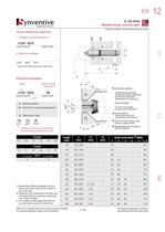
tr.row {} td.cell {} div.block {} div.paragraph {} .font0 { font:4.80pt "Arial", sans-serif; } .font1 { font:5.60pt "Arial", sans-serif; } .font2 { font:6.00pt "Arial", sans-serif; } .font3 { font:7.00pt "Arial", sans-serif; } .font4 { font:9.00pt "Arial", sans-serif; } .font5 { font:10.00pt "Arial", sans-serif; } .font6 { font:11.00pt "Arial", sans-serif; } .font7 { font:15.00pt "Arial", sans-serif; } .font8 { font:25.00pt "Arial", sans-serif; } .font9 { font:31.00pt "Arial", sans-serif; } Rynventive molding solutions 12 E01 K01Np|P] Manifold nozzle, screw fit, open 2a Illustrations simplified,...
Open the catalog to page 8All Synventive Molding Solutions catalogs and technical brochures
 Series 06 S
4 Pages
 Series 12 S
4 Pages
 Mixing & Filter Nozzles
12 Pages


Archived catalogs
 Examples of Hot Runners in use
20 Pages
 Hot Runner Systems
7 Pages
 Manifold Nozzles, Threaded
5 Pages
 Manifolds VH
6 Pages
 Manifolds VF
6 Pages
 Manifolds VC
45 Pages
 Manifolds VD
6 Pages
 Manifolds VE
6 Pages
 Manifolds VI
6 Pages
 Hot Runner Guide
34 Pages
 Threaded / Screw Fit 22 E02
17 Pages
 Threaded / Screw Fit T16
16 Pages
 Support Ring / Face Fit SR16
16 Pages
 Threaded / Screw Fit 16 E01
17 Pages
 Support Ring / Face Fit 04 C01
16 Pages
 Support Ring / Face Fit 04 C03
16 Pages
 Support Ring / Face Fit SR8
11 Pages
 Dynamic Feed
14 Pages
 Support Ring / Face Fit SR24
14 Pages
 Support Ring / Face Fit SR20
22 Pages
 Machine Nozzles
12 Pages
 Threaded / Screw Fit 07 E01
15 Pages
 Hot Halves
6 Pages
 Threaded / Screw Fit 16 E02
17 Pages
 Threaded / Screw Fit 22 E01
17 Pages
 Valve Gate
20 Pages
 Threaded / Screw Fit T20
21 Pages
 Threaded / Screw Fit T24
13 Pages






- Actuator
- Linear actuator
- Digital temperature control
- Liquid nozzle
- Temperature controller
- Digital temperature controller
- Pack unit
- Automation temperature controller
- Electric hydraulic power unit
- Multi-channel manifold
- Pneumatic actuator
- Industrial tip
- Temperature control unit
- Double-acting actuator
- Digital temperature control unit
- Plastic nozzle
- Control actuator
- Compact hydraulic power unit
- Hydraulic actuator