Catalog excerpts
Company C > Products P > Technology T > Application A >
Open the catalog to page 1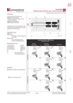
Illustrations simplified, schematically drawn and not to scale. Product type Manifold nozzle sliding fit > D D1 Utilizes heat pipe technology to ensure uniform temperature > Dt 訨 Patented seal technology Replaceable threaded tipsAvailable with ten Controlled Vestige (CV) tip options including valve gates for zero vestige applications. See table at right.Available gating types > Gate Major Dimensions (mm) Full flow 訨 Cone point:CV11CM & CV21CM developed for PA and PBT Valve gate: VG12 & VG23 tapered gate VG12S & VG23S Straight gate VG-23SGate:5.0 > L1 J Z J Nozzle length106-500Nozzle flow...
Open the catalog to page 2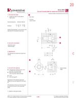
Illustrations simplified, schematically drawn and not to scale. 1. Cut out for the nozzle 2. Cut out for connections3. Alignment pin 1 > * drawn offset** to all other pocket surfaces DIN ISO 2768-mK > 3.21.60.8 2 > H6 Dt 3 ؠ electrical power > 14 53 0.03 Ѡ thermocouple > J 0.05 6 The alignment pin prevents the nozzle from rotating. > 26 2 > 20 4. Cut out for the nozzle tip > H6 break all sharpedges 6 DtHA)b) Tip јHot runner gate Through bore nozzle tip (CV10, CV11, CV11CM, VG12 and VG12SBlind bore nozzle tip (CV20, CV21,CV21CM, VG23 & VG23S) Length from back of cavity plate toGate...
Open the catalog to page 4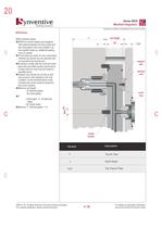
Illustrations simplified, schematically drawn and not to scale. SR20 Series SR20 manifold criteria: > SR20 hot runner systems are designed with preload between the thrust pads and the mold plates in the cold condition. As the manifold heats an additional sealing force is created > T TCP656 訨 > 訨 Thrust pads are made of a low conductivity material and should only be replaced with an equivalent Synventive part Excessive contact with the mold will cause heat sinks and affect system performance. Contact with the mold must be limited to specified areas. Support ring nozzles do not line up with...
Open the catalog to page 5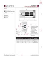
Illustrations simplified, schematically drawn and not to scale. SR20 CV11 > D D1 General: Filled and unfilled materials More heat in gate area for semi-crystalline materials 訨 Heat pipes for isothermal operation Nozzle Criteria: > Orifice 2.0-4.0 蘨 J length 106-500 Patented seal > L1 J Z 2-4 Information regarding H6 蘰 26 tolerances and surfaces 30 120 ఘ shape and position tolerances cut out for connections ࠠ groove/bore for locking pinplease see page 3 Cut out in mould plate for nozzle and connectionsӔGeneral tolerances according to DIN ISO 2768-mK 2-4 Heater zones power (Watt) 3) 45 ذ...
Open the catalog to page 8All Synventive Molding Solutions catalogs and technical brochures
-
Series 06 S
4 Pages
-
Series 12 S
4 Pages
-
Mixing & Filter Nozzles
12 Pages
Archived catalogs
-
Manifold Nozzles, Threaded
5 Pages
-
Hot Runner Systems
7 Pages
-
Examples of Hot Runners in use
20 Pages
-
heated pipe hot runner system
1 Pages
-
Valve Gate
20 Pages
-
Hot Halves
6 Pages
-
Dynamic Feed
14 Pages
-
Hot Runner Guide
34 Pages
-
Machine Nozzles
12 Pages
-
Manifolds VI
6 Pages
-
Manifolds VH
6 Pages
-
Manifolds VF
6 Pages
-
Manifolds VE
6 Pages
-
Manifolds VD
6 Pages
-
Manifolds VC
45 Pages
-
Threaded / Screw Fit T24
13 Pages
-
Threaded / Screw Fit T20
21 Pages
-
Threaded / Screw Fit T16
16 Pages
-
Threaded / Screw Fit 22 E02
17 Pages
-
Threaded / Screw Fit 22 E01
17 Pages
-
Threaded / Screw Fit 16 E02
17 Pages
-
Threaded / Screw Fit 16 E01
17 Pages
-
Threaded / Screw Fit 12 E01
17 Pages
-
Threaded / Screw Fit 07 E01
15 Pages
-
Support Ring / Face Fit SR24
14 Pages
-
Support Ring / Face Fit SR16
16 Pages
-
Support Ring / Face Fit SR8
11 Pages
-
Support Ring / Face Fit 04 C03
16 Pages
-
Support Ring / Face Fit 04 C01
16 Pages


