- Catalogs
- Synventive Molding Solutions
- Hot Runner System Connections
Hot Runner System Connections
1 /6Pages

Hot Runner System Connections
1 /6Pages
Catalog excerpts

Connections and supply Connections and Supply Lines lines for hot runner systems for Hot Runner Systems Illustrations simplified, schematically drawn and not to scale. 2006-08-19 - All rights reserved. Errors and omissions excepted. For a specific application, please consult Synventive. For design and application information, see the Synventive Hot Runner Guide.
Open the catalog to page 1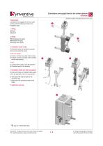
Connections and supply lines for hot runner systems Overview Illustrations simplified, schematically drawn and not to scale. Product type Connections and supply lines for hot runner systems with the following functions and installation types: 1. Wiring Power è Signals è 2. Piping è Compressed air supply è Hydraulic oil supply è water supply Cooling 3. Installation inside mould All wires and hoses are installed in grooves and cut outs inside the mould. Power and signals a) Heaters and thermocouples of the nozzles b) Heaters and thermocouples of the manifold and the inlet bushing Hoses c) Cooling...
Open the catalog to page 2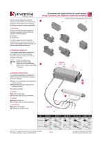
Connections and supply lines for hot runner systems Wiring: Connectors, pin assignment, heater zone numbering Illustrations simplified, schematically drawn and not to scale. When hot runner systems are wired the selection of the connectors as well as the pin assigment and the heater zone numbering are done according to customer specification. 1. Connectors Shown on the right there are examples for connector inserts and housing as they are used for hot runner systems. a) Pin insert b) Socket insert For power supply e g at the temperature controller socket inserts have to be used in order to avoid...
Open the catalog to page 3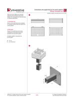
Connections and supply lines for hot runner systems Wiring: Connection box Illustrations simplified, schematically drawn and not to scale. When hot runner systems are wired the selection of the connection box and the design of the wire guards are done according to customer specification. 1. Connection box Shown on the right there are two examples for conection boxes as they are used for hot runner systems. 2. Wire guard Shown on the right there are the basic components of wire guards which are mounted to the hot runner system. a) Retainer plate for connection box b) Wire guard w 41 mm h 41 /...
Open the catalog to page 4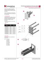
Connections and supply lines for hot runner systems Piping: Connection plate and hose guard Illustrations simplified, schematically drawn and not to scale. When hot runner systems are piped the installation of hoses and the design of the hose guard are done according to customer specification. Shown on the right there are the basic hose guard components which are mounted to the hot runner system. 3 1. Connection plate The plate with room for 6 fittings as shown on the right is the basic element for all connection plates. The assignment of the connections is done according to customer specification....
Open the catalog to page 5
Connections and supply lines for hot runner systems Illustrations simplified, schematically drawn and not to scale. 2006-08-19 - All rights reserved. Errors and omissions excepted. For a specific application, please consult Synventive. MK-PRM.BRM.GB-P.CONCTN 2009-05-01 For design and application information, see the Synventive Hot Runner Guide.
Open the catalog to page 6All Synventive Molding Solutions catalogs and technical brochures
 Series 06 S
4 Pages
 Series 12 S
4 Pages
 Mixing & Filter Nozzles
12 Pages


Archived catalogs
 Examples of Hot Runners in use
20 Pages
 Hot Runner Systems
7 Pages
 Manifold Nozzles, Threaded
5 Pages
 Manifolds VH
6 Pages
 Manifolds VF
6 Pages
 Manifolds VC
45 Pages
 Manifolds VD
6 Pages
 Manifolds VE
6 Pages
 Manifolds VI
6 Pages
 Hot Runner Guide
34 Pages
 Threaded / Screw Fit 22 E02
17 Pages
 Threaded / Screw Fit T16
16 Pages
 Support Ring / Face Fit SR16
16 Pages
 Threaded / Screw Fit 16 E01
17 Pages
 Support Ring / Face Fit 04 C01
16 Pages
 Support Ring / Face Fit 04 C03
16 Pages
 Support Ring / Face Fit SR8
11 Pages
 Dynamic Feed
14 Pages
 Support Ring / Face Fit SR24
14 Pages
 Support Ring / Face Fit SR20
22 Pages
 Machine Nozzles
12 Pages
 Threaded / Screw Fit 07 E01
15 Pages
 Threaded / Screw Fit 12 E01
17 Pages
 Hot Halves
6 Pages
 Threaded / Screw Fit 16 E02
17 Pages
 Threaded / Screw Fit 22 E01
17 Pages
 Valve Gate
20 Pages
 Threaded / Screw Fit T20
21 Pages
 Threaded / Screw Fit T24
13 Pages


- AMOT digital temperature control
- Liquid nozzle
- AMOT digital temperature controller
- Screw-in single nozzle
- Industrial tip
- Temperature control unit
- Plastic nozzle
- Digital temperature control unit
- Programmable temperature controller
- Injection nozzle
- Compact temperature control
- Heating temperature control unit
- Hot runner nozzle
- Polypropylene nozzle
- Automation temperature control unit
- Modular temperature control
- Industrial temperature control unit
- Melt nozzle