- Catalogs
- Syntron Material Handling
- Working with Hoppers
Working with Hoppers
1 /28Pages

Working with Hoppers
1 /28Pages
Catalog excerpts
Syntron® Working with Hoppers
Open the catalog to page 1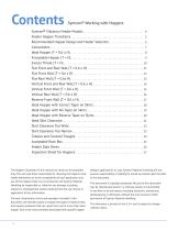
Syntron® Working with Hoppers Syntron® Vibratory Feeder Models . . . . . . . . . . . . . . . . . . . . . . . . . . . . . . . . . . . . . . . . . . . . . 4 Feeder Hopper Transitions . . . . . . . . . . . . . . . . . . . . . . . . . . . . . . . . . . . . . . . . . . . . . . . . . . . . . 5 Recommended Hopper Design and Feeder Selection . . . . . . . . . . . . . . . . . . . . . . . . . . 6 Calculations . . . . . . . . . . . . . . . . . . . . . . . . . . . . . . . . . . . . . . . . . . . . . . . . . . . . . . . . . . . . . . . . . . . . 7 Ideal Hopper (T = 0.6 x H) . . . . . . . . . . . . . . . ....
Open the catalog to page 2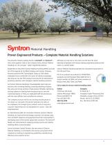
Proven Engineered Products – Complete Material Handling Solutions Two powerful industry leading brands—Link-Belt® and Syntron®— have come together under a new company name, Syntron Material Handling, LLC, for one goal – better engineered products. Although we may have a new name, we still have the same dedicated employees and industry leading engineered products that make us a market leader. Established in May 2014, Syntron Material Handling (SMH) was built out of the legacies of Link-Belt Company and Syntron Company, formerly owned by FMC Technologies. Today, our 300 skilled employees have a...
Open the catalog to page 3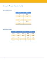
Syntron® Vibratory Feeder Models Light-Duty Feeders Heavy-Duty Feeders
Open the catalog to page 4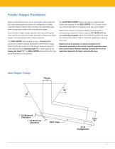
Feeder Hopper Transitions Material characteristics such as size distribution, shear properties and cohesiveness generally dictate the configuration of feeder transition hoppers. Material flow velocities vary, depending upon material properties, feeder stroke and operating speed. Good transition hopper design optimizes flow rate, allowing the most economical choice of a feeder. Improperly designed transition hoppers will substantially reduce feeder capacities. The IDEAL HOPPER, illustrated below, has a T/H ratio of 0.6 and shows a uniform material flow pattern to the feeder trough. Material at...
Open the catalog to page 5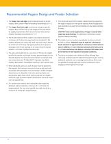
Recommended Hopper Design and Feeder Selection 1. The hopper rear wall angle must be steep enough to permit material flow. Syntron Material Handling recommends 60° ± 2°. 2. The hopper front wall angle must be just enough to permit material flow. The flow rate on the hopper front wall should be slightly less than the flow rate on the back wall. Syntron Material Handling recommends 55° ± 2°. 3. The throat dimension T for random size material should be a minimum of 2 times the largest particle of material. If the material particles are nearly the same size (near size), T should be a minimum of 4...
Open the catalog to page 6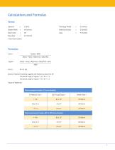
Calculations and Formulas Terms Capacity Discharge Depth Material Density Gate Factor Flow Rate Syntron Material Handling suggests the following values for GF: If material angle of repose > 35°, GF = 1.3 If material angle of repose < 35°, GF = 1.5 *Value of R (ft/min) Electromagnetic Feeders (F Series Models) Electromechanical Feeders (RF or MF Series Models)
Open the catalog to page 7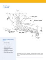
Benefits of Ideal Hopper Design: • Uniform Flow Pattern • Maximum Capacity • Maximum Material Velocity • Maximum Material Depth • Optimized Feeder Size • Reduced potential for material build-up at inlet • Reduced potential for spillage at back and sides • Reduced material load on feeder *Active material area required to achieve ideal uniform flow patterns. If less, flow pattern will not be uniform and there will be the potential for excess material loads and reduced capacity. 8
Open the catalog to page 8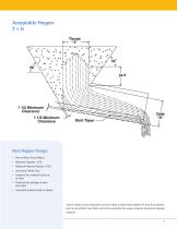
Ideal Hopper Design: • Non-uniform Flow Pattern • Reduced Capacity ~15% • Reduced Material Velocity ~10% • Increased Feeder Size • Potential for material build-up at inlet • Potential for spillage at back and sides • Increased material load on feeder *Active material area required to achieve ideal uniform flow patterns. If less, flow pattern will not be uniform and there will be the potential for excess material loads and reduced capacity. 9
Open the catalog to page 9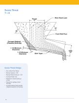
Excess Throat Design: • Non-uniform Flow Pattern • Reduced Capacity > 20% • Reduced Material Velocity > 15% • Increased Feeder Size • Potential for material build-up at inlet • Potential for spillage at back and sides • Increased material load, possible collapsed suspension coil springs
Open the catalog to page 10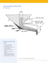
Flat Front Wall and Rear Wall T = 0.6 x H Flat Front and Rear Wall Design: • Non-uniform Flow Pattern • Reduced Capacity > 20% • Reduced Material Velocity > 15% • Increased Feeder Size • Potential for material build-up at inlet • Potential for spillage at back and sides • Increased material load, possible collapsed suspension coil springs • Reduced depth at discharge > 10% For T = H and T > H, all conditions will be compounded. 11
Open the catalog to page 11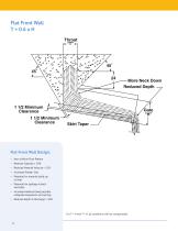
Flat Front Wall T = 0.6 x H Flat Front Wall Design: • Non-uniform Flow Pattern • Reduced Capacity > 20% • Reduced Material Velocity > 15% • Increased Feeder Size • Potential for material build-up at inlet • Potential for spillage at back and sides • Increased material load, possible collapsed suspension coil springs • Reduced depth at discharge > 10% For T = H and T > H, all conditions will be compounded. 12
Open the catalog to page 12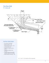
Flat Rear Wall T = 0.6 x H Flat Rear Wall Design: • Non-uniform Flow Pattern • Reduced Capacity > 20% • Reduced Material Velocity > 15% • Increased Feeder Size • Potential for material build-up at inlet • Potential for spillage at back and sides • Increased material load, possible collapsed suspension coil springs • Reduced depth at discharge > 10% For T = H and T > H, all conditions will be compounded. 13
Open the catalog to page 13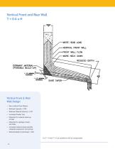
Vertical Front and Rear Wall T = 0.6 x H Vertical Front & Rear Wall Design: • Non-uniform Flow Pattern • Reduced Capacity > 20% • Reduced Material Velocity > 15% • Increased Feeder Size • Potential for material build-up at inlet • Potential for spillage at back and sides • Increased material load, possible collapsed suspension coil springs • Reduced depth at discharge > 10% For T = H and T > H, all conditions will be compounded. 14
Open the catalog to page 14All Syntron Material Handling catalogs and technical brochures
 Syntron® Vibrating Conveyors
24 Pages
 Vibrating Screens Catalog
36 Pages
 Screw Conveyor Catalog
6 Pages
 Bin Vibrator Catalog
30 Pages
 Paper Joggers Catalog
20 Pages
 Material Handling
2 Pages
 Vibrator Flowaids
30 Pages
 Syntron Vibrating Tables
6 Pages
 Syntron Vibrators
48 Pages
 Syntron Screen Feeders
6 Pages
 Belt Conveyor Idler
160 Pages
 Syntron High Velocity
2 Pages
 Syntron Jogger
20 Pages
 Syntron Vibrating Screens
36 Pages
 CEMA Series E4000 Idlers
36 Pages
 CEMA Series C2000 Idlers
22 Pages
 CEMA Series B2000 Idlers
22 Pages
 Ball Bearing Idlers
8 Pages
 Working with Isolation
20 Pages
 Aggregates
20 Pages
 Coal Handling
20 Pages
 Syntro-Flo
2 Pages
 Link-Belt Bucket Elevator
26 Pages
 Syntron Power Pulse Control
2 Pages
 C2000
C20002 Pages
 Link-Belt Screw Conveyor
101 Pages
 Link-Belt Underground
32 Pages
 Link-Belt Idler
160 Pages
 Syntron® Vibrators
48 Pages


Archived catalogs
 PowerPulse WT
2 Pages
 HV-10
HV-102 Pages
- Bourn And Koch conveyor
- Bourn And Koch transport conveyor
- Bourn And Koch belt conveyor
- Bourn And Koch horizontal conveyor
- Rolling bearing
- Steel bearing
- Bourn And Koch screener
- Conveyor for the food industry
- Ball bearing
- Bourn And Koch bulk material screener
- Inclined conveyor
- Bourn And Koch handling conveyor
- Roller bearing
- Vibration motor
- Conveyor roller
- Bulk material conveyor
- Bourn And Koch vibrating screener
- Screw conveyor
- Metal conveyor roller