PQ60 series
1 /14Pages

PQ60 series
1 /14Pages
Catalog excerpts

Technical Specification Half 100 Amp, No Heatsink, Isolated DC/DC Converter The PQ60012HPAA0 PowerQor™ Peta converter is a next-generation, board-mountable, isolated, fixed switching frequency DC/DC converter that uses synchronous rectification to achieve extremely high conversion efficiency. The power dissipated by the converter is so low that a heatsink is not required, which saves cost, weight, height, and application effort. The Peta series converters offer industry leading output current for a standard “half-brick” module. The Peta units also feature active current sharing for N+1 and parallel applications. Operational Features • Ultra-high efficiency, >88% half load, >83% full load • Delivers up to 100 amps of output current with minimal derating - no heatsink required • Wide input voltage range: 35V – 75V, with 100V 100ms input voltage transient withstand • Fixed frequency switching provides predictable EMI performance Mechanical Features • Industry standard pin-out configuration • Industry standard size: 2.3” x 2.4” • Total height only 0.43”, permits better airflow and smaller card pitch • Total weight: 2.9 oz. (83 grams) Safety Features • 2000V, 30 MΩ input-to-output isolation • UL 60950 recognized (US & Canada), basic insulation rating • TUV certified to EN60950 • Meets 72/23/EEC and 93/68/EEC directives • Meets UL94V-0 flammability requirements Product # PQ60012HPAA0 Protection Features • Input under-voltage lockout disables converter at low input voltage conditions • Output current limit and short circuit protection • Output over-voltage protection • Thermal shutdown Control Features • On/Off control referenced to input side (positive and negative logic options are available) • Remote sense for the output voltage compensates for output distribution drops • Output voltage trim permits custom voltages and voltage margining Optional Features (Full-Feature modules) • Active current share for N+1 and parallel applications • External Clock Synchronization pin for better EMI characteristics • Startup Synchronization pin for more consistent startup sequence Doc.# 005-2HP621K Rev. B
Open the catalog to page 1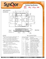
Technical Specification Half Brick MECHANICAL DIAGRAM Bottom side Clearance Side View Lowest Component Load Board 1) Pins 1-4, 7-9, A-B are 0.040” (1.02mm) diameter. with 0.080” (2.03mm) diameter standoff shoulders. 2) Pins 5-6, 10-11 are 0.080” (2.03 mm) diameter with 0.125” (3.18mm) diameter standoff shoulders. 3) Pins 3, A, & B only included in Full-Feature models. 4) Other pin extension lengths available. Recommended pin length is 0.03” (0.76mm) greater than the PCB thickness. 5) All Pins: Material - Copper Alloy Finish - Tin/Lead over Nickel plate 6) Undimensioned components are shown for...
Open the catalog to page 2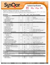
Technical Specification Half Brick PQ60012HPAA0 ELECTRICAL CHARACTERISTICS TA=25°C, airflow rate=300 LFM, Vin=48Vdc unless otherwise noted; full operating temperature range is -40°C to +100°C ambient temperature with appropriate power derating. Specifications subject to change without notice. Notes & Conditions ABSOLUTE MAXIMUM RATINGS Input Voltage Non-Operating Operating Operating Transient Protection Isolation Voltage (input to output) Operating Temperature Storage Temperature Voltage at ON/OFF input pin Voltage at Clock Sync pin INPUT CHARACTERISTICS Operating Input Voltage Range Input Under-Voltage...
Open the catalog to page 3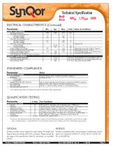
Technical Specification Half ELECTRICAL CHARACTERISTICS (Continued) Parameter P Switching Frequency ON/OFF Control (Option P) Off-State Voltage On-State Voltage ON/OFF Control (Option N) Off-State Voltage On-State Voltage ON/OFF Control (Either Option) Pull-Up Voltage Pull-Up Resistance Output Voltage Trim Range Output Voltage Remote Sense Range Output Over-Voltage Protection Over-Temperature Shutdown Over-Temperature Shutdown Restart Hysteresis FEATURE CHARACTERISTICS RELIABILITY CHARACTERISTICS Calculated MTBF (Telcordia) Calculated MTBF (MIL-217) Demonstrated MTBF Notes & Conditions Figures...
Open the catalog to page 4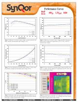
Performance Curves Half Figure 1: Efficiency at nominal output voltage vs. load current for minimum, nominal, and maximum input voltage at 25°C. Figure 2: Efficiency at nominal output voltage and 60% rated power vs. airflow rate for ambient air temperatures of 25°C, 40°C, and 55°C (nominal input voltage). 14.0 Figure 3: Power dissipation at nominal output voltage vs. load current for minimum, nominal, and maximum input voltage at 25°C. Figure 4: Power dissipation at nominal output voltage and 60% rated power vs. airflow rate for ambient air temperatures of 25°C, 40°C, and 55°C (nominal input...
Open the catalog to page 5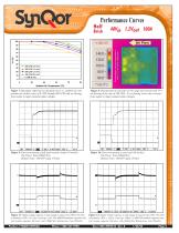
Performance Curves Half Semiconductor junction temperature is within 1°C of surface temperature Figure 7: Maximum output power derating curves vs. ambient air temperature for airflow rates of 0 LFM through 400 LFM with air flowing from output to input (nominal input voltage). Figure 8: Thermal plot of converter at 94.5 amp load current with 55°C air flowing at the rate of 200 LFM. Air is flowing across the converter from output to input (nominal input voltage). Figure 9: Turn-on transient at full load (resistive load) (10 ms/div). Top Trace: Vout (500mV/div) Bottom Trace: ON/OFF input (5V/div)...
Open the catalog to page 6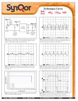
Performance Curves Half source impedance DC/DC Converter ceramic 450mΩ ESR capacitor tantalum capacitor electrolytic capacitor Figure 13: Test set-up diagram showing measurement points for Input Terminal Ripple Current (Figure 14), Input Reflected Ripple Current (Figure 15) and Output Voltage Ripple (Figure 16). Figure 14: Input Terminal Ripple Current, ic, at full rated output current and nominal input voltage with 10µH source impedance and 47µF electrolytic capacitor (100 mA/div). (See Figure 13) Figure 15: Input reflected ripple current, is, through a 10 µH source inductor at nominal input...
Open the catalog to page 7All SYNQOR catalogs and technical brochures
 SynQor
108 Pages
 VPX
VPX6 Pages
 UPS MS 1500
6 Pages
 MQFL-270L-05S
19 Pages
 MQFL-28VE-1R5S
15 Pages
 MQFL-28V-1R5S
17 Pages
 MQFL-28E-1R5S
19 Pages
 MQFL-28-1R5S
19 Pages
 PQ60012SMx25
15 Pages
 PQ40 Series
16 Pages
 PQ30 series
14 Pages
 PQ24018QGx25
16 Pages
 SUMMER 2011 Product Catalog
52 Pages
 MilQor Mil-COTS Brochure
6 Pages
 MilQor Hi-Rel Brochure
6 Pages
- Power supply unit
- DC power supply
- AC/DC power supply
- Single-output power supply
- Electronic filter
- Passive electronic filter
- Multiple-output power supply
- AC electronic filter
- Single-output DC/DC converter module
- Isolated DC-DC converter
- Low-pass electronic filter
- Industrial DC/DC converter module
- SMD DC-DC converter
- Power supply for medical applications
- Three-phase electronic filter
- EMI filter
- Rugged DC/DC converter
- Dual-output DC/DC converter module
- Panel-mount power supply