PQ30 series
1 /14Pages

PQ30 series
1 /14Pages
Catalog excerpts

Quar ter-brick The PQ300 33QGA30 PowerQor™ Giga quarter-brick converter is a next-generation, board-mountable, isolated, fixed switching frequency DC/DC converter that uses synchronous rectification to achieve extremely high conversion efficiency. The PQ30 module offers a wide input voltage range to cover both 24V and 48V applications. The power dissipated by the converter is so low that a heatsink is not required, which saves cost, weight, height, and application effort. All of the power and control components are mounted to the multi-layer PCB substrate with high-yield surface mount technology for greater reliability. RoHS 5/6 Compliant (see page 12). Operational Features • High efficiency, 89.5%(24Vin); 88.5%(48Vin) at full rated load current • Delivers up to 30 amps of output current with minimal derating - no heatsink required • Wide input voltage range: 19V – 60V, with 80V 100ms input voltage transient capability • Fixed frequency switching provides predictable EMI performance • No minimum load requirement means no preload resistors required Mechanical Features • Industry standard quarter-brick pin-out configuration • Industry standard size: 1.45” x 2.3” (36.8x58.4mm) • Total height only 0.412” (10.46mm), permits better airflow and smaller card pitch • Total weight: 1.2 oz. (34 grams) • Flanged pins designed to permit surface mount soldering (avoid wave solder) using FPiP technique Contr ol Features • On/Off control referenced to input side (positive and negative logic options are available) • Remote sense for the output voltage compensates for output distribution drops • Output voltage trim permits custom voltages and voltage margining Product # PQ30033QGA30 PQ30033QGA30 Module Pr otection Features • Input under-voltage lockout disables converter at low input voltage conditions • Output current limit and short circuit protection protects converter and load from permanent damage and consequent hazardous conditions • Active back bias limit prevents damage to converter from external load induced pre-bias • Output over-voltage protection protects load from damaging voltages • Thermal shutdown protects converter from abnormal environmental conditions Safety Features • 2000V, 30 MΩ input-to-output isolation provides input/output ground separation • UL/cUL 60950 recognized (US & Canada), basic insulation rating • TUV certified to EN60950 • Meets 72/23/EEC and 93/68/EEC directives which facilitates CE Marking in user’s end product • Board and plastic components meet UL94V-0 flammability requirements
Open the catalog to page 1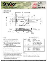
Input: Output: Current: Package: Technical Specification MECHANICAL DIAGRAM Max. Height Bottom side Clearance Side View Load Board 1) Pins 1-3, 5-7 are 0.040” (1.02mm) diameter with 0.080” (2.03 mm) diameter standoff shoulders. 2) Pins 4 and 8 are 0.062” (1.57 mm) diameter with 0.100” (2.54 mm) diameter standoff shoulders. 3) Other pin extension lengths available. Recommended pin length is 0.03” (0.76mm) greater than the PCB thickness. 4) All Pins: Material - Copper Alloy Finish - Tin/Lead over Nickel plate 5) Undimensioned components are shown for visual reference only. 6) All dimensions in...
Open the catalog to page 2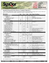
Input: Output: Current: Package: Technical Specification TA=25°C, airflow rate=300 LFM, Vin=48Vdc unless otherwise noted; full operating temperature range is -40°C to +100°C ambient temperature with appropriate power derating. Specifications subject to change without notice. Notes & Conditions Continuous Continuous 100ms transient, square wave Basic insulation, Pollution Degree 2 ABSOLUTE MAXIMUM RATINGS Input Voltage Non-Operating Operating Operating Transient Protection Isolation Voltage (input to output) Operating Temperature Storage Temperature Voltage at ON/OFF input pin INPUT CHARACTERISTICS...
Open the catalog to page 3
Input: Output: Current: Package: Technical Specification ELECTRICAL CHARACTERISTICS (Continued) Parameter P FEATURE CHARACTERISTICS Switching Frequency ON/OFF Control (Option P) Off-State Voltage On-State Voltage ON/OFF Control (Option N) Off-State Voltage On-State Voltage ON/OFF Control (Either Option) Pull-Up Voltage Pull-Up Resistance Output Voltage Trim Range (See note 3 below) Output Voltage Remote Sense Range Output Over-Voltage Protection Over-Temperature Shutdown Over-Temperature Shutdown Restart Hysteresis Load Current Scale Factor RELIABILITY CHARACTERISTICS Calculated MTBF (Telcordia)...
Open the catalog to page 4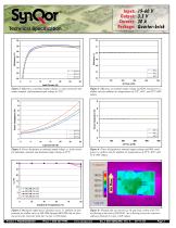
Input: Output: Current: Package: Figure 1: Efficiency at nominal output voltage vs. load current for minimum, nominal, and maximum input voltage at 25°C. Figure 2: Efficiency at nominal output voltage and 60% rated power vs. airflow rate for ambient air temperatures of 25°C, 40°C, and 55°C (48V input). Figure 3: Power dissipation at nominal output voltage vs. load current for minimum, nominal, and maximum input voltage at 25°C. Figure 4: Power dissipation at nominal output voltage and 60% rated power vs. airflow rate for ambient air temperatures of 25°C, 40°C, and 55°C (48V input). Figure 5:...
Open the catalog to page 5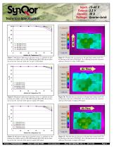
Input: Output: Current: Package: Technical Specification Figure 7: Maximum output power derating curves vs. ambient air temperature for airflow rates of 100 LFM through 400 LFM with air flowing across the converter from pin 3 to pin 1 (48V input). Figure 8: Thermal plot of converter at 30 amp load current with 55°C air flowing at the rate of 200 LFM. Air is flowing across the converter sideways from pin 3 to pin 1 (48V input). Figure 9: Maximum output power derating curves vs. ambient air temperature for airflow rates of 100 LFM through 400 LFM with air flowing across the converter from input...
Open the catalog to page 6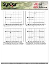
Input: Output: Current: Package: Technical Specification Semiconductor junction temperature is within 1°C of surface temperature Figure 13: Turn-on transient at full load (resistive load) (5 ms/div). Input voltage pre-applied. Ch 1: Vout (1V/div). Ch 2: ON/OFF input (5V/div). Figure 14: Turn-on transient at zero load (5 ms/div). Ch 1: Vout (1V/div). Ch 2: ON/OFF input (5V/div). Figure 15: Output voltage response to step-change in load current (50%75%-50% of Iout(max); dI/dt = 0.1A/µs). Load cap: 10µF, 100 mΩ ESR tantalum cap and 1µF ceramic cap. Ch 1: Vout (200mV/div), Ch 2: Iout (10A/div). Figure...
Open the catalog to page 7All SYNQOR catalogs and technical brochures
 SynQor
108 Pages
 VPX
VPX6 Pages
 UPS MS 1500
6 Pages
 MQFL-270L-05S
19 Pages
 MQFL-28VE-1R5S
15 Pages
 MQFL-28V-1R5S
17 Pages
 MQFL-28E-1R5S
19 Pages
 MQFL-28-1R5S
19 Pages
 PQ60012SMx25
15 Pages
 PQ60 series
14 Pages
 PQ40 Series
16 Pages
 PQ24018QGx25
16 Pages
 SUMMER 2011 Product Catalog
52 Pages
 MilQor Mil-COTS Brochure
6 Pages
 MilQor Hi-Rel Brochure
6 Pages
- Power supply unit
- DC power supply
- AC/DC power supply
- Single-output power supply
- Electronic filter
- Passive electronic filter
- Multiple-output power supply
- AC electronic filter
- Single-output DC/DC converter module
- Isolated DC-DC converter
- Low-pass electronic filter
- Industrial DC/DC converter module
- SMD DC-DC converter
- Power supply for medical applications
- Three-phase electronic filter
- EMI filter
- Rugged DC/DC converter
- Dual-output DC/DC converter module
- Panel-mount power supply