
- Catalogs
- SUZHOU VEICHI Electric Co., Ltd.
- AC60 series frequency inverter


AC60 series frequency inverter

1 / 191 PagesView full catalog
AC60 series frequency inverter
Product catalog summary
Foreword
The AC60 series frequency inverter by Veich Electric Co. LTD is designed for high-torque, precision, and reliability across a wide speed range. It includes a simplified PLC, PID adjustor, and various control interfaces, suitable for equipment matching, automation control, and industrial applications.
The AC60 series frequency inverter by Veich Electric Co. LTD is designed for high-torque, precision, and reliability across a wide speed range. It includes a simplified PLC, PID adjustor, and various control interfaces, suitable for equipment matching, automation control, and industrial applications.
Safety Requirements and Cautions
Emphasizes safety during installation, operation, and maintenance. Key points include:
Emphasizes safety during installation, operation, and maintenance. Key points include:
- Only qualified personnel should operate the equipment.
- Install on nonflammable materials and avoid explosive environments.
- Ensure proper wiring and grounding to prevent electric shock.
- Do not modify the inverter without authorization.
Purchase Inspection and Product Specification
Inspect for transportation damage and verify nameplate details against your order. The AC60 series undergoes rigorous testing before leaving the factory.
Inspect for transportation damage and verify nameplate details against your order. The AC60 series undergoes rigorous testing before leaving the factory.
Installation
Guidelines include environmental requirements, mounting directions, and space considerations to ensure effective heat dissipation and safe operation.
Guidelines include environmental requirements, mounting directions, and space considerations to ensure effective heat dissipation and safe operation.
Frequency Inverter Wiring
Details on wiring attentions, basic wiring diagrams, and terminal specifications are provided to ensure safe and efficient electrical connections.
Details on wiring attentions, basic wiring diagrams, and terminal specifications are provided to ensure safe and efficient electrical connections.
Keyboard Operation and Usage
Covers the layout and functions of the keyboard, including operation modes and indicator lamp meanings.
Covers the layout and functions of the keyboard, including operation modes and indicator lamp meanings.
Functional Parameter Table
Lists basic, exterior terminal, and special function parameters necessary for configuring the inverter.
Lists basic, exterior terminal, and special function parameters necessary for configuring the inverter.
Function Detailed Specification
Provides detailed descriptions of basic parameters, external terminal parameters, and special function parameters.
Provides detailed descriptions of basic parameters, external terminal parameters, and special function parameters.
Abnormality Diagnoses and Processing
Includes fault information, troubleshooting methods, and common fault processing techniques.
Includes fault information, troubleshooting methods, and common fault processing techniques.
Overhaul and Maintenance
Guidelines for inspection, maintenance, and periodic replacement of components to ensure longevity and reliability.
Guidelines for inspection, maintenance, and periodic replacement of components to ensure longevity and reliability.
Optional Parts
Describes optional components such as alternating current reactors, noise filters, and braking units.
Describes optional components such as alternating current reactors, noise filters, and braking units.
Quality Guarantee
Outlines the "Three guarantee" service, lifelong paid service, and service provider responsibilities.
Outlines the "Three guarantee" service, lifelong paid service, and service provider responsibilities.
Appendix
Includes the RS485 communication protocol for advanced users.
Includes the RS485 communication protocol for advanced users.
Specifications
Includes voltage and frequency specifications, frequency control range, voltage/frequency characteristics, carrier frequency, torque upgrade, maximum capacity, acceleration/deceleration time, rated output voltage, automatic functions, and protection functions.
Includes voltage and frequency specifications, frequency control range, voltage/frequency characteristics, carrier frequency, torque upgrade, maximum capacity, acceleration/deceleration time, rated output voltage, automatic functions, and protection functions.
Installation Requirements
Includes environmental conditions, installation modes, and safety precautions for wiring and operation.
Includes environmental conditions, installation modes, and safety precautions for wiring and operation.
Operation and Maintenance
Guidelines for using control terminals or keyboard for operation, ensuring proper installation of noise filters, and regular checks for electromagnetic interference.
Guidelines for using control terminals or keyboard for operation, ensuring proper installation of noise filters, and regular checks for electromagnetic interference.
Electrical Specifications Recommendation
Provides a detailed table of electrical specifications for various models of the AC60 series frequency inverters.
Provides a detailed table of electrical specifications for various models of the AC60 series frequency inverters.
Control Circuit Terminals
Outlines the sequence and functions of control circuit terminals, including input and output signals.
Outlines the sequence and functions of control circuit terminals, including input and output signals.
RS485 Communication Mode
Details robust communication capabilities, allowing communication with PCs or PLCs.
Details robust communication capabilities, allowing communication with PCs or PLCs.
Keyboard Operation and Usage
Describes the keyboard layout and functions for single and double display types.
Describes the keyboard layout and functions for single and double display types.
Parameter Setting and Functional Parameter Table
Uses a menu structure for parameter settings, allowing quick inquiry and modification.
Uses a menu structure for parameter settings, allowing quick inquiry and modification.
Technical Document Summary
Speed and Direction Control
Outlines control of speed and direction through various steps, each with specific parameters for operation time and direction control.
Outlines control of speed and direction through various steps, each with specific parameters for operation time and direction control.
Communication and Control Settings
Specifies settings for communication protocols and control settings.
Specifies settings for communication protocols and control settings.
Frequency and Channel Selection
Describes the selection of main and auxiliary channels for frequency input.
Describes the selection of main and auxiliary channels for frequency input.
Frequency Gain and Combination
Explains how to adjust frequency input through gain settings and channel combinations.
Explains how to adjust frequency input through gain settings and channel combinations.
Additional Specifications
Includes detailed parameter settings for executing commands, frequency given channels, and communication timeout settings.
Includes detailed parameter settings for executing commands, frequency given channels, and communication timeout settings.
Specifications and Settings
Includes terminal VS2 configuration, LED display selection, keyboard function selection, frequency limits, acceleration and deceleration, V/F curve mode, carrier frequency, slip frequency compensation, energy saving, and voltage regulation.
Includes terminal VS2 configuration, LED display selection, keyboard function selection, frequency limits, acceleration and deceleration, V/F curve mode, carrier frequency, slip frequency compensation, energy saving, and voltage regulation.
Power Cut Restart Function
Details settings for power cut restart selection and waiting time.
Details settings for power cut restart selection and waiting time.
Free Stop Frequency
The inverter decelerates to a set frequency before stopping.
The inverter decelerates to a set frequency before stopping.
DC Braking
Provides torque at zero speed for enhanced stop accuracy.
Provides torque at zero speed for enhanced stop accuracy.
Jump Frequency
Avoids resonance by setting up to three jump frequencies.
Avoids resonance by setting up to three jump frequencies.
Fault Auto-Restore
Allows automatic reset after certain faults.
Allows automatic reset after certain faults.
Operation Direction
Options to set consistent, opposite, or prohibit reverse operation.
Options to set consistent, opposite, or prohibit reverse operation.
Cooling Fan Options
Modes for fan operation based on temperature and inverter state.
Modes for fan operation based on temperature and inverter state.
Frequency Protection Mode
Includes over-voltage stall protection, grounding short circuit detection, input open-phase protection, and overload/overheat protection modes.
Includes over-voltage stall protection, grounding short circuit detection, input open-phase protection, and overload/overheat protection modes.
Electronic Heat-Sensitive Coefficient
Sets the thermal relay protection coefficient for motor overload protection.
Sets the thermal relay protection coefficient for motor overload protection.
Specifications
Outlines various parameters for frequency inverters, including electronic thermal coefficients, stall protection, energy-consumed braking, and motor settings.
Outlines various parameters for frequency inverters, including electronic thermal coefficients, stall protection, energy-consumed braking, and motor settings.
Procedures
Instructions for setting parameters include setting nameplate parameters, adjusting inverter output voltage ratio, and using G/P modules setting for different load types.
Instructions for setting parameters include setting nameplate parameters, adjusting inverter output voltage ratio, and using G/P modules setting for different load types.
Norms and Recommendations
Recommendations include installing thermal protection relays, adjusting parameters if the limiting current function is active, and carefully setting energy-consumed braking action voltage values.
Recommendations include installing thermal protection relays, adjusting parameters if the limiting current function is active, and carefully setting energy-consumed braking action voltage values.
Monitoring and Fault Information
Provides a detailed description of monitoring codes and fault information.
Provides a detailed description of monitoring codes and fault information.
External Terminal Parameters
Details on input signal selection and action modes for control terminals.
Details on input signal selection and action modes for control terminals.
Overview This document provides detailed technical specifications and operational procedures for a frequency inverter, focusing on control methods, step speed settings, and input/output configurations.
Control Methods The frequency inverter can be controlled via keyboard, terminal, or RS485.
Terminal Operation Mode After a fault reset, the terminal operation mode can be set to either power on directly or require a power-off before starting.
Rotational Control Options include standard rotational control, double linear, and three linear rotational controls.
Step Speed Settings The inverter supports up to 15 step speed settings.
Acceleration and Deceleration Times Multiple acceleration and deceleration times can be set.
Output Terminal Functions Various output signals can be configured.
Voltage Input Settings Details settings for VS1 and VS2 terminal input voltages.
Additional Features Includes parameters for timer settings, counter values, and bipolar control adjustments.
Specifications and Procedures
Outlines the operational parameters and settings for a frequency inverter.
Outlines the operational parameters and settings for a frequency inverter.
Input and Output Terminal Settings
Defines settings for AS and PUL terminals.
Defines settings for AS and PUL terminals.
Control Functions
Includes bipolar control and PID control.
Includes bipolar control and PID control.
Special Functions
Includes free-setting V/F curve and keyboard potentiometer.
Includes free-setting V/F curve and keyboard potentiometer.
Recommendations and Best Practices
Ensure proper configuration of terminal connections and software settings.
Ensure proper configuration of terminal connections and software settings.
Overview This document provides detailed technical specifications and operational guidelines for a frequency inverter system.
Differential Adjustment Used to manage feedback signal changes.
Sampling Period (H-22) The sampling period for feedback quantity.
PID Control Deviation Limit (H-23) Limits the maximum offset of PID feedback.
Start and Dormancy Thresholds (H-24, H-25) Define conditions for starting or entering dormancy.
Alarm Limits (H-26, H-27) Set to trigger alarms when PID feedback exceeds thresholds.
Sensor Disconnection Detection (H-28, H-29) Detects open circuits in sensors.
Program Running Modes (H-32) Various modes define how the frequency inverter operates.
Power Down Memory (H-34) Determines whether the system saves its state during a power down.
Step Speed Settings (H-35 to H-49) Configure direction and acceleration/deceleration times.
Communication Settings (H-66 to H-73) Includes settings for machine address, data format, baud rate, and response delay.
Abnormality Diagnoses and Processing
Fault Information and Troubleshooting Provides a detailed table of fault codes, types, possible reasons, and troubleshooting steps.
Common Fault and Processing Methods Categorizes common faults and provides specific troubleshooting methods.
Overhaul and Maintenance
Inspection and Maintenance Regular inspections are crucial for preventing issues.
Components Needed Periodic Replacement Certain components require periodic replacement.
Preservation and Maintenance Guidelines for storing frequency inverters.
Measurement and Judgment Instructions for using ohmmeters and multimeters.
Optional Parts Discusses optional parts like AC reactors, noise filters, braking units, and capacitance boxes.
Quality Guarantee Outlines the "three guarantee" service.
Appendix
RS485 Communication Protocol Introduces the RS485 communication protocol for the AC60 series frequency inverter.
ModBus Serial Communication Protocol Outlines the ModBus serial communication protocol for the AC60 series frequency inverter.
Protocol Content Defines asynchronous transfer information content and formats.
Application Styles Connects to a control network with a single host and multiple slave machines.
Bus Configuration Uses an RS485 hardware interface in a synchronized serial, half-duplex transmission mode.
Protocol Specification The communication protocol is a master-slave ModBus protocol.
Communication Frame Structure The data format is RTU mode.
Command Codes and Data Description Various command codes are defined for reading and writing data.
Error Check Mode Uses odd/even checking for each character and CRC-16 for frame data.
Communication Data Address Definition Addresses are defined for controlling the frequency inverter.
Frequency Inverter Fault Codes A table of fault codes is provided.
Overvoltage and Overcurrent Issues
Deceleration Overvoltage (o.U.2) Occurs during the deceleration phase.
Constant Speed Overvoltage (o.U.3) Happens when maintaining a constant speed.
Close-down Overvoltage (o.U.4) Detected during shutdown.
Acceleration Overcurrent (o.C.1) Occurs during acceleration.
Deceleration Overcurrent (o.C.2) Happens during deceleration.
Constant Speed Overcurrent (o.C.3) Detected at constant speed.
Overload and Fault Conditions
Motor Overload (o.L.1) Indicates motor is overloaded.
Frequency Inverter Overload (o.L.2) Overload in the frequency inverter.
System Fault (Sc) General system fault.
Frequency Inverter Inner Overheating (o.H.) Overheating inside the inverter.
Feedback Sensor Fault (Sen) Fault in the feedback sensor.
Missing Phase at Input Side (Err1) Phase missing at input.
Output Grounding (Err2) Grounding issue at output.
Current Detection Fault (Err3) Fault in current detection.
Frequency Inverter Exterior Fault (Err4) External fault in the inverter.
Swing Frequency Running Parameter Setting Fault (Err5) Error in setting swing frequency parameters.
Keyboard Communication Fault (Err6) Communication issue with the keyboard.
Storage Error (93SE) Error related to storage.
Error Codes for Slave Machine Abnormal Responses
Command Code Error Incorrect command code.
Communication Transmission Error Error in communication transmission.
CRC Checking Error Error in CRC checking.
Illegal Address Address is not valid.
Illegal Data Data is not valid.
Parameter Change During Running Parameter changed while running.
System Locked System is locked.
Frequency Inverter Busy Inverter is busy, EEPROM is storing.
Parameter Overrun Parameter exceeds limits.
Reserved Parameter Cannot Be Changed Reserved parameters are immutable.
Read Parameter Byte Error Error in reading parameter byte.
See more
All SUZHOU VEICHI Electric Co., Ltd. catalogs and technical brochures
 AC01 Series Network AC Drive
12 Pages
 V9E General Servo Motor Catalog
19 Pages
 VEICHI Pump Drive Catalog
12 Pages
 SD700 Series
14 Pages
 solar pump system
12 Pages
 VC Series PLC
6 Pages
 VI20 Series HMI
6 Pages
 VI10 Human Machine Interface
35 Pages
 PLC-catalog
35 Pages
 AC310-XL special inverter
8 Pages
 EHS100-integrated-servo
8 Pages
 S200 series three-phase AC drive
14 Pages
 QT-tower-crane-integrated-drive
14 Pages
 AC70T-hoist-special-inverter
14 Pages
 Solar Pump Inverter
6 Pages
 Product Catalog
18 Pages
 ac drive
2 Pages
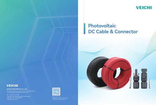

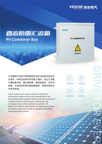
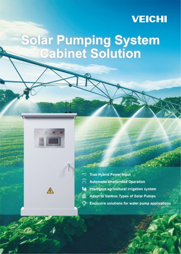


Archived catalogs
 CO2 MIG/ NBC WELDING MACHINE
2 Pages
 welding machine
15 Pages
 plasma cutting machine
2 Pages

Related Searches
- Pump
- Industrial pump
- Pump with electric motor
- Stationary pump
- Seawater pump
- Connector
- Centrifugal pump
- Self-priming pump
- Power supply unit
- DC power supply
- Electrical cable
- Stainless steel pump
- AC/DC power supply
- Industrial robot
- Submersible pump
- Rectangular housing
- Electrical power supply connector
- Transfer pump
- Compact pump
- Copper cable
*Prices are pre-tax. They exclude delivery charges and customs duties and do not include additional charges for installation or activation options. Prices are indicative only and may vary by country, with changes to the cost of raw materials and exchange rates.
About DirectIndustry
DirectIndustry is a marketplace that offers B2B players a complete experience, from product sourcing to purchase. DirectIndustry is an entity of VirtualExpo Group.
Are you a buyer?
Are you a supplier?