- Catalogs
- SUZHOU VEICHI Electric Co., Ltd.
- ac01-network-type-ac-drive-manual-v1.1.pdf
- Company
- Products
- Catalogs
- News & Trends
- Exhibitions
ac01-network-type-ac-drive-manual-v1.1.pdf
1 /63Pages

ac01-network-type-ac-drive-manual-v1.1.pdf
1 /63Pages
Catalog excerpts

AC01-Series network inverter manual
Open the catalog to page 1
AC01-Series network inverter manual
Open the catalog to page 2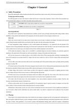
AC01-Series network inverter manual Chapter 1 General 1.1 Safety Precautions Please fully understand the safety precautions described in this manual before using to ensure safety of both persons and products. Warning signs and their meanings The following marks are used in this manual to indicate that this part is of great safety importance. Failure to follow these precautions may result in personal injury, damage or even death to the product and associated systems. DANGER: death or major safety accidents may occur due to wrong operations. Caution: minor injuries may occur due to wrong operations....
Open the catalog to page 3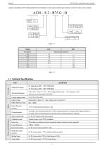
AC01-Series network inverter manual company immediately. After confirming that the received product is intact, please confirm again whether you received what you have ordered. Power input Item Voltage & Frequency Lower than rated current Output voltage Rated output: 3 phase, 0V ~ input voltage, error lower than 5% Output frequency range Output frequency accuracy ±0.5% of the maximum frequency value Overload capacity T3 model: 150% of rated current for 89 s, 180% of rated current for 10 seconds, 200% rated current for 3 s S2 model: 150% of rated current for 24 seconds, 180% of rated current for...
Open the catalog to page 4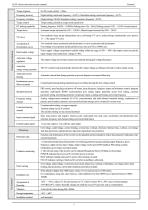
AC01-Series network inverter manual Frequency accuracy Digital setting: maximum frequency ×±0.01%; Simulation setting: maximum frequency ×±0.2% Frequency resolution Digital setting: 0.01Hz; Simulation setting: maximum frequency ×0.05% Torque control Torque setting calculation, torque mode speed limit Starting frequency: 0.00Hz ~ 50.00Hz; Braking time: 0.0s ~ 60.0s; Braking current: 0.0% ~ 150.0% of rated current Torque boost Automatic torque increased by 0.0% ~ 100.0%; Manual torque increased by 0.0% ~ 30.0% Four methods: linear torque characteristic curve, self-setting V/F curve, reduced torque...
Open the catalog to page 5
AC01-Series network inverter manual Protection level Pollution level Cooling method Natural cooling for models with V1 cases Forced air cooling for models with V2 and V3 cases Table 1- 3
Open the catalog to page 6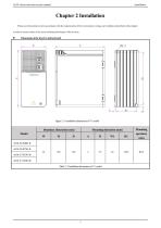
AC01-Series network inverter manual Chapter 2 Installation Please use the product in strict accordance with the requirements of the environment, wiring, and ventilation described in this chapter. in order to ensure safety of the users and best performance of the inverter. Dimensions of the inverter and keyboard Figure 2- 1 Installation dimensions of V1 model
Open the catalog to page 7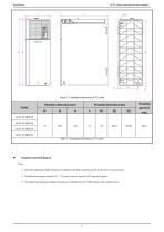
AC01-Series network inverter manual Figure 2- 2 Installation dimensions of V2 model Standard connection diagram Note: 1. Select the appropriate brake resistance according to the field conditions and Brake Resistance Specifications; 2. Multifunctional input terminals (X1 ~ X3) can be used as input for NPN transistor signals; 3. The digital and analog grounding terminals are combined into the COM terminal in the control circuit;
Open the catalog to page 8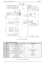
AC01-Series network inverter manual Figure 2- 3 Standard connection diagram Auxiliary terminals and output capacity Terminal +10V Function a loop formed with a 10V auxiliary analog power output and COM a loop formed with a 24V auxiliary digital power output and COM digital and analog power supply digit input terminal Collector open output & programmable action object. TATC: normally on; TB TC: normally off Passive contact output & programmable action object. Current analog input Voltage analog input RS485 communication terminal Table 2- 3 Auxiliary terminals and output capacity
Open the catalog to page 9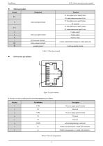
AC01-Series network inverter manual Main loop terminal Symbol Function T3: three-phase power input R phase S2: single-phase power input L line T3: three-phase power input S phase main loop input terminal S2: reserved T3: three-phase power input T phase S2: single-phase power input N wire U-phase output main loop output terminal V-phase output W-phase output brake resistance terminal Used on external brake resistance to realize quick stop ground terminal Used to ground the inverter Table 2- 4 Main loop terminal Figure 2- 4 RJ45 interface It’s the top view above and the specific network interpretations...
Open the catalog to page 10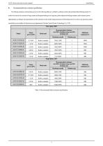
AC01-Series network inverter manual Recommended brake resistance specifications The braking resistance and resistance power in the following table are verified by ordinary inertia load and intermittent braking mode. If it needs to be used in the occasion of large inertia and frequent braking for a long time, please adjust the braking resistance and resistance power appropriately according to the specifications of the selected inverter and the rated parameters of the braking unit. If you have any questions, please consult the service hotline of technical service department of Suzhou Veichi Electric...
Open the catalog to page 11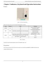
AC01-Series network inverter manual Indicators, Keyboard Layout and Operation Instructions Chapter 3 Indicators, Keyboard and Operation Instructions Indicators Figure 3- 1 AC01 series main interface States ofAC01 Series inverters can be told via the three indicating lights on its interface: Symbol Power on, and ready for operation Abnormal power supply The inverter runs in positive rotation Flash (500ms on and then 500ms off,and cycle starts again) Inverter runs in reverse Faults of main codes 1~11 occur Flash (100ms on and then 100ms off,and cycle starts again) FAULT Faults of main codes 12~117...
Open the catalog to page 12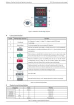
Indicators, Keyboard Layout and Operation Instructions AC01-Series network inverter manual Figure 3- 2 KBD300-25 dual-line display keyboard External keyboard functions Symbol Dual-line display keyboard Unit indicator Functions Hz: Frequency;A: current; V: voltage; V/A: voltage or current; RPM: speed; Status indicator %: percentage. On: forward running; flash: reverse running; Off: shutdown. Enter the menu interface when standby or running. Press the key to exit the modification after parameters are modified and long press the key for 1 second to directly enter the status interface. Run When...
Open the catalog to page 13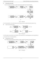
AC01-Series network inverter manual Indicators, Keyboard Layout and Operation Instructions Basic parameter group setting Take F0.122 [acceleration time] setting as an example to illustrate the basic operations of the external LED keyboard. \ Figure 3- 3 Setting steps Note: The keyboard shift key on the external keyboard can be used to quickly select the tens, hundreds and thousands of parameter values. Operation monitoring status checking Figure 3- 4 Checking steps Note: When using the external keyboard, use the left shift key to cycle switch the first row of monitoring parameters, and use...
Open the catalog to page 14All SUZHOU VEICHI Electric Co., Ltd. catalogs and technical brochures
 AC01 Series Network AC Drive
12 Pages
 V9E General Servo Motor Catalog
19 Pages
 VEICHI Pump Drive Catalog
12 Pages
 SD700 Series
14 Pages
 solar pump system
12 Pages
 VC Series PLC
6 Pages
 VI20 Series HMI
6 Pages
 VI10 Human Machine Interface
35 Pages
 PLC-catalog
35 Pages
 AC310-XL special inverter
8 Pages
 EHS100-integrated-servo
8 Pages
 S200 series three-phase AC drive
14 Pages
 QT-tower-crane-integrated-drive
14 Pages
 AC70T-hoist-special-inverter
14 Pages
 Solar Pump Inverter
6 Pages
 Product Catalog
18 Pages
 ac drive
2 Pages
 AC60 series frequency inverter
191 Pages


Archived catalogs
 CO2 MIG/ NBC WELDING MACHINE
2 Pages
 welding machine
15 Pages
 plasma cutting machine
2 Pages

- EMA pump
- EMA industrial pump
- EMA electric pump
- EMA stationary pump
- EMA water pump
- Connector
- EMA centrifugal pump
- EMA self-priming pump
- EMA DC power supply
- EMA AC/DC power supply
- Electrical cable
- EMA stainless steel pump
- EMA industrial robot
- Rectangular housing
- EMA submersible pump
- EMA transfer pump
- Electrical power supply connector
- Compact pump
- Metal connector