
- Catalogs
- Suzhou Honpine Precision Industry Co., Ltd.
- HONPINE harmonic drive catelog


- Company
- Products
- Catalogs
- News & Trends
- Exhibitions
HONPINE harmonic drive catelog
HONPINE harmonic drive catelog
Suzhou Honpine Precision Industry Co., Ltd specializes in precision motion control solutions, offering products such as Strain Wave Gear, frameless motors, and precision components. With over a decade of experience, Honpine ensures high-quality products by managing the entire production process in-house. Their products are widely used in advanced industrial fields like robotics and aerospace.
The catalog details various models of Strain Wave Gear, categorized by size and type, including Standard, High Torque, and Lightweight models. Each model is available in different ratios, showcasing their versatility in applications.
Strain Wave Gears consist of three main components: Wave generator, flexspline, and circular spline. The gear operates by deforming the flexspline into an elliptical shape, engaging and disengaging teeth with the circular spline to transmit motion. Key characteristics include high accuracy, high reduction ratio, high torque capacity, and compact size.
The document provides detailed technical specifications, including improvements in tooth profile for increased torque capacity and reduced temperature rise. Definitions of terms like starting torque, permissible peak torque, and angle transmission accuracy are provided to aid in understanding gear performance.
A flowchart guides the selection of the appropriate model based on average load torque and input speed requirements. Considerations for maximum moment load and static safety coefficient are also discussed.
Sections on assembly precautions, grease lubricant use, and sealing mechanisms provide guidelines for maintaining optimal gear performance. Specifications for main roller bearings and starting torque are also included.
The catalog includes detailed introductions and technical data for various series like FS, FH, and FHD, along with outline drawings for each model.
Warranty, trademark, and safety use information are provided, emphasizing the importance of adhering to recommended practices for safe and effective use of the products.
The document outlines the operational conditions and model number determination for a Wave generator. It includes checks for permissible peak torque, maximum momentary torque, and calculated lifetime against the life of the Wave generator. The document also details calculations for permissible number of impacts, average output rotational speed, reduction ratio, and input rotational speeds.
The Wave generator features a European-style coupling with self-aligning and rigid types. It discusses axial force directions during acceleration and deceleration and provides guidelines for customizing the hole diameter of the Wave generator.
Instructions are provided for connecting and fixing the Wave generator, including methods for different input shaft configurations. The document emphasizes the importance of correct assembly to prevent damage and ensure smooth operation. It includes specific precautions for the Wave generator, circular spline, and flexspline.
The document stresses the importance of using the correct grease for Strain Wave Gear to ensure proper operation and longevity. It provides guidelines for grease storage, application, and replacement, along with specific filling quantities for different models.
Details on the sealing mechanism for the screw, including seal and groove dimensions for various models, are provided to ensure proper sealing and prevent leakage.
The document provides detailed specifications for various series of bearings and components, including FS, FSD, FFS, FH, FHD, and FHT series. Each series is described with parameters such as pitch circle diameter, bias amount, basic rated dynamic and static loads, allowable static moment, and starting torque values. The document emphasizes the importance of using grade 12.9 screws with thread locker to prevent failure or looseness during operation.
It is recommended to ensure the recommended accuracy for the FHT-I/II series to fully utilize their performance. The document also advises using sealant during assembly when groove space is insufficient. For the FS series, the unit type structure includes components like the output flange, circular spline, cross roller bearing, wave generator, and flexspline.
The document specifies the locking torque values for different screw sizes and highlights the need for precise installation to achieve optimal performance. It also provides guidelines for checking the main roller bearing, including maximum load moment load, lifespan, and static safety coefficient.
The tables in the document provide comprehensive data on the specifications of various series, including the basic rated dynamic and static loads, allowable static moments, and starting torque values. The tables also include information on reduction ratios, rated torque at input, permissible peak torque, and permissible maximum input rotational speed.
All connecting and fixing screws should be of grade 12.9 and coated with thread locker. The seal groove on the circular spline is already machined, and no further machining is required by the client. The document also highlights the importance of using the specified grease and adhering to installation size requirements.
- Use the grease specified by the company.
- The asterisk (*) in the drawing indicates installation reference size; adhere to these size requirements.
- If product performance parameters are not specified, refer to the latest company catalog for standard values.
- Wave Generator Models: Various models with specific dimensions and tolerances (e.g., φ6, φ8, φ11, etc.).
- Reduction Ratios: Different models offer reduction ratios such as 50, 80, 100, 120, 160, etc.
- Rated Torque: Varies by model and reduction ratio, e.g., 16 Nm for model 17 at a 50 reduction ratio.
- Permissible Peak Torque: Specified for start/stop conditions, e.g., 34 Nm for model 17 at a 50 reduction ratio.
- Permissible Maximum Input Rotational Speed: Typically 3500 r/min for most models.
- Design Life and Backlash: Design life is generally ≥10000 hours with a backlash of ≤20 Arc Sec.
- Instantaneous Permissible Maximum Torque: Varies by model, e.g., 70 Nm for model 17 at a 50 reduction ratio.
- Permissible Average Input Rotational Speed: Generally 7300 r/min for most models.
- FSF-17-XX-U-I and FSF-20-XX-U-I: Detailed specifications for these models include torque values, permissible speeds, and design life.
- FSF-25-XX-U-I and FSF-40-XX-U-I: Higher torque and load capacities compared to smaller models.
- FSN Series: Includes models like FSN-5-XX-U-I and FSN-8-XX-U-I with lower torque values suitable for different applications.
- Models and Reduction Ratios: The document details various models such as FHG-20, FHG-25, FHG-32, FHG-40, etc., each with different reduction ratios (50, 80, 100, 120, 160).
- Torque Specifications: Each model specifies rated torque at 2000 r/min input, permissible peak torque at start/stop, maximum average load torque, and maximum momentary torque. For example, the FHG-20 model with a reduction ratio of 50 has a rated torque of 33 Nm and a permissible peak torque of 73 Nm.
- Rotational Speed: The permissible maximum input rotational speed is consistently 3500 r/min across models, with average input rotational speeds varying based on the model and reduction ratio.
- Design Life and Backlash: Design life is specified in hours, typically ≥10000 or ≥15000, with backlash ≤20 Arc Sec.
- Weight: The weight of each model is provided in kg, varying with the model and reduction ratio.
- Use the grease specified by the company.
- Follow installation reference sizes marked with an asterisk (*) in the drawings.
- If performance parameters are unspecified, refer to the latest company catalog for standard values.
- The tables provide detailed mechanical specifications for different gear models, focusing on torque capacities, rotational speeds, and design life, essential for selecting the appropriate model for specific applications.
The document outlines the technical specifications for various models of the FH Series, including reduction ratios, rated torque at 2000 r/min input, permissible peak torque at start/stop, permissible maximum value for average load torque, instantaneous permissible maximum torque, permissible maximum input rotational speed, permissible average input rotational speed, backlash, weight, and design life. These specifications are provided in both Nm and kgf·m units, with rotational speeds in r/min and backlash in arc seconds.
1. Use the grease specified by the company.
2. Follow the installation reference size indicated by the asterisk (*) in the drawings.
3. If product performance parameters are not specified, refer to the latest company catalog for standard values.
The products are warranted against defects in workmanship and materials for one year after delivery or 2,000 hours of operation, whichever is shorter. The warranty covers maintenance or replacement due to manufacturing defects but excludes damages from unsuitable operation, unauthorized modifications, external causes, or natural disasters. The warranty is specific to Honpine products and does not cover consequential damages or labor costs for installation.
The product is not suitable for use in space flight facilities, aircraft equipment, nuclear power equipment, domestic homes, vacuum equipment, automotive equipment, personal recreation equipment, equipment that directly works on human bodies, transport of humans, or special environments. Consultation with authorized personnel is advised for these applications.
Improper use or handling could result in a risk of death or serious injury. Caution is advised when using the product.
Ensure to read the catalog thoroughly when designing equipment. Use the products only in suitable environments, adhering to specified conditions such as ambient temperature (0-40°C), and avoiding exposure to water, oil, corrosive gases, or dust.
Follow precise assembly and installation instructions as per the catalog. Use recommended fastening methods to prevent issues like vibration or product failure. Ensure installation accuracy to avoid deterioration of precision and lifespan.
Use only specified lubricants to maintain product lifespan. Factory lubrication should not be mixed with other greases. Replace lubricants as recommended.
Avoid using forceful methods like hammering on parts. Do not exceed allowable torque limits to prevent malfunction. Avoid altering or disassembling components to maintain performance.
Wear protective gear to prevent contact with eyes or skin. Do not ingest grease. Handle waste oil and containers according to regulations.
In case of contact with eyes or skin, wash thoroughly and seek medical treatment if necessary. Do not induce vomiting if ingested.
Seal products tightly after use to prevent contamination. Dispose of products according to industrial waste standards.
Suzhou Honpine Precision Industry Co., Ltd.
Email: [email protected]
Website: www.honpine.com
Phone: +86-18994329920
Catalog excerpts
STRAIN WAVE GEAR Reducer for precision control General Catalog
Open the catalog to page 1
About Us Suzhou Honpine Precision Industry Co., Ltd is committed to becoming a leading supplier of precision motion control solu tions. We have developed Strain Wave Gear, frameless motors, encoders, drives, precision bearings, and more—these developments have resulted in three major business segments: Strain Wave Gear, rotary actuators, and precision comp onents. With over 10 years of profound industry experience, Honpinehas grown into a comprehensive, solution-oriented enterprise, evolving from a single-component manufacturer to a full-solution provider in precision motion control. Currently,...
Open the catalog to page 2
Product Lineup 06 Introduction of FSD Principle of Strain Wave Gear 08 Outline Drawing of fsd Technical Information Precautions on Grease Lubricant 19 Checking Main Roller Bearing 23 Main Roller Bearing Specifications 24 Technical Data of FHT/FHN/FHG 66 Outline Drawing of FHT/FHN/FHG 69 Technical Data of FSS/FFS/FSN/FSG 30 Outline Drawing of FSS/FFS/FSN/FSG 33
Open the catalog to page 3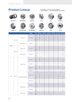
Product Lineup • Available — This is currently available. o Not Available — This is temporarily not available. FSS/FSG-C-I FSS/FSN/FSG-I
Open the catalog to page 4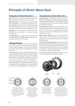
Principle of Strain Wave Gears Principle of Strain Wave Gear Composition of Strain Wave Gear Characteristics of Strain Wave Gear Strain Wave Gear consist of three basic components: Wave generator, flexspline and circular spline. High Accuracy: A significant portion of the teeth are always engaged in two zones 180 degrees apart. This neutralizes the effects of tooth pitch errors and accumulated pitch errors, ensuring high positional and rotational accuracy. Wave generator: it is made up of a wave bearing and an elliptical cam. The Wave generator is usually attached to the input end. The inner...
Open the catalog to page 6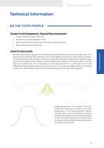
Technical Information • Torque capacity increase 15%-30% • Temperature rise decreased by 8-10°C • Minimize the tooth surface contact area prone to fatigue pitting • Service life exceeds 15,000 hours Technical Information About FS tooth profile We have made several upgrades to the traditional theoretical double-arc profile. The original two-curve continuous arc profile has been optimized into a multi-segment continuous arc with varying curvatures. This ensures proper gear meshing in the reducer while reducing relative sliding friction, thereby mitigating the risk of grease failure caused by grease...
Open the catalog to page 7
Technical Information TERMS AND DEFINITIONS ■ Starting Torque It is the minimum torque value applied to the input end at which the strain wave gear first starts to rotate with no load. ■ Maximum Average Input Speed It is the average value of input speed. ■ Permissible Peak Torque for Start and Stop It is the maximum torque as a result of the moment of inertia of the output load during acceleration and deceleration. ■ Permissible Maximum Momentary Torque It is the momentary peak torque the strain wave gear may be subjected to the event of a collision or emergency stop. It indicates allowable continuous...
Open the catalog to page 8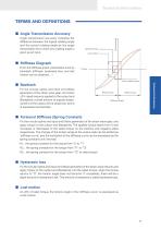
Technical Information Angle transmission accuracy indicates the difference between the logical rotating angle and the actual rotating angle as the angle transmission error when any rotating angle is given as an input. Torsional angel Angle Transmission Accuracy Hysteresis loss Lost motion Stiffness Diagraph From the stiffness graph, parameters such as backlash, stiffness, hysteresis loss, and lost motion can be obtained. → Fix the circular spline and input end (Wave generator) of the strain wave gear, and when ±2% rated torque is applied to the output end (flexspline), a small amount of angular...
Open the catalog to page 9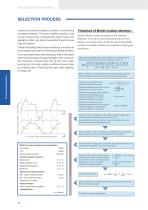
Technical Information SELECTION PROCESS Flowchart of Model number selection In general, the servo system is rarely in a continuous constant loadstate. The input rotational speed, load torque change and comparatively large torque are applied at start and stop.Unexpected impact torque may be applied. Select a Model number according to the following flowchart. If you find a value exceeding that from the ratings, you should review it with the upper-level Model number or consider reduction of conditions including the load torque. These fluctuating load torques should be converted to the average load...
Open the catalog to page 10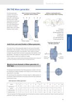
Technical Information ON THE Wave generator Basic structure and shape of Wave generator shown as below. The Wave generator includes a structure of a European-style coupling with a self-aligning structure and an rigid type without an automatic self-aligning structure and varies depending on the series. For details, please refer to the outline drawing of each series. Oldham coupling Structure Utiling a European Style Coupling ① Retainer ② Wave bearing ③ Wave generator Plug ④ Insert hole ⑤ Rubwasher ⑦ Wave generator hub Oldham coupling Rigid type Axial force direction of the Wave generator Axial...
Open the catalog to page 11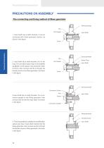
Technical Information PRECAUTIONS ON ASSEMBLY The connecting and fixing method of Wave generator Wave generator Key Flat Gasket Technical Information 1. Input shaft has a shaft shoulder, it can be connected with Wave generator directly. As shown in the figure. 2. Input shaft has a shaft shoulder, but it‘s too long. You can add a space ring on the shaft(the parallelism of the spacer ring should be within 0.01mm), then connect and fix it through the thimble screw on the Wave generator. As shown in the figure. Input Shaft Flat Gasket Wave generator Space Ring Input Shaft Wave generator Connection...
Open the catalog to page 12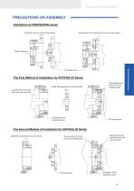
Technical Information PRECAUTIONS ON ASSEMBLY Installation of FSS/FSG/FSN series Install the reducer as the arrow shows Seal between the input fixed end and circular spline Output Terminal The First Method of Installation for FHT/FHG-I/II Series Install Wave generator as arrow shows Seal between the input fixed end and flexspline Fill grease in the flexspline cavity Seal between the output end and circular spline Fill grease here The Second Method of Installation for FHT/FHG-I/II Series Install Wave generator as arrow shows Seal between the input fixed end and flexspline Fill grease here Seal...
Open the catalog to page 13All Suzhou Honpine Precision Industry Co., Ltd. catalogs and technical brochures
 High Precision Planetary Gearbox
48 Pages
 mini harmonic drive reducer
27 Pages
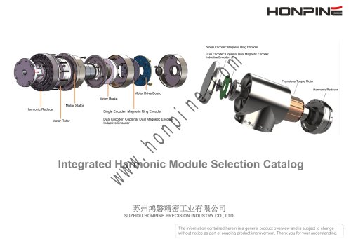 Harmonic Rotary Module
14 Pages
 Dexterous Robot Hand
8 Pages
 HONPINE Precision Motion Control
17 Pages
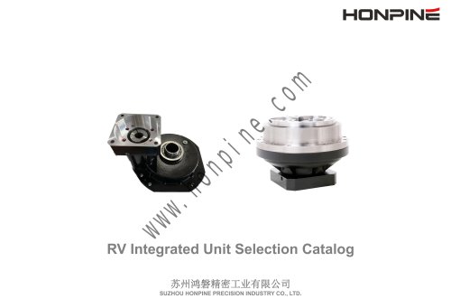 RV Reducer Gearbox
15 Pages
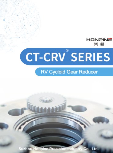 Robot RV Cycloid Gear Reducer
58 Pages
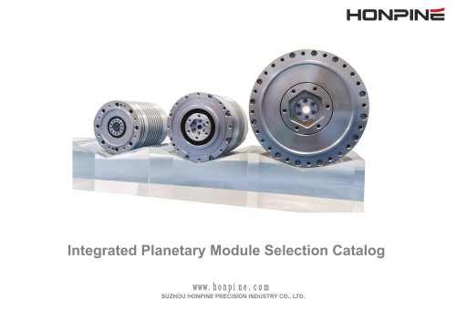 Planetary Robot Joint Actuator
14 Pages
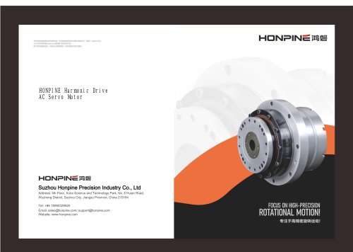 Harmonic AC Servo Motor
33 Pages
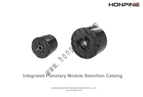
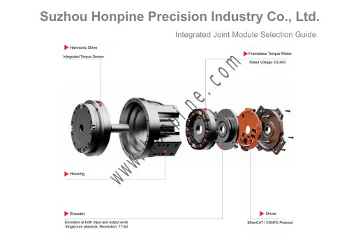
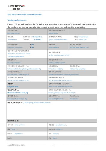
- Electromotor
- Synchronous motor
- Industrial robot
- Electric gearmotor
- Linear actuator
- Planetary gearbox
- Electric actuator
- Coaxial gearhead
- Mechanical protection protection gloves
- EC motor
- Electromotor for industrial applications
- Articulated robot
- Precision gearhead
- 24 V motor
- Servo-motor
- 6-axis robot
- Right angle gearhead
- Direct current gear-motor
- Compact gearhead