- Catalogs
- Sunfab Hydraulics
- variable flow hydraulic pump
variable flow hydraulic pump

variable flow hydraulic pump
Catalog excerpts

3115 GB Pump SVH 062, 092, 112 The Sunfab variable displacement pump with its rugged construction is designed for direct mounting at the auxiliary drive (P.T.O.) of commercial vehicles. flow is dependent on the present drive speed and geometric displacement. The flow is adjust ble in a a range between 0 and Qmax. Long service life is ensured due to the pressurized lubWith a max. displacement rication of the swash plate of 112 cm3/rev. and a peak bearing shell. pressure of 400 bar it is Sunfab SVH is rotationsuited for many applicadirection dependent and tions. This is complemented by the high self priming should be ordered in either right-hand or left-hand rate and the low noise designs. level. The pump delivery Other advantages of Sunfab SVH: • Short reaction time when resetting the flow • Compact installation dimensions • High pressure • Externally drained for best cooling • Rugged construction and long service life • Low noise emission • Low power-to-weightratio 1
Open the catalog to page 1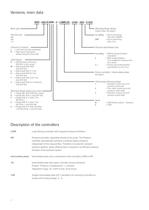
Versions, main data SVH - 092 R DZN - 2 - LSNR/ZL - 2/65 - 350 - C 022 Basic type Mounting flange design Nominal size 062 092 112 no coding UNF Direction of rotation: Pressure specification (bar) Shaft design: no coding 2 2 /... (output side), see page 5 L = Left-hand (counter clockwise) R = Right-hand (clockwise) always facing the drive shaft D M S H T U = Splined shaft conforming DIN ISO 14 (for trucks) = Spline shaft DIN 5480 only SVH 092 = Spline shaft SAE-C J 744 = Spline shaft SAE-B J 744 only SVH 062 = Spline shaft SAE-B-B J 744 only SVH 062 = Spline shaft SAE-B J 744(short) only SVH 062...
Open the catalog to page 2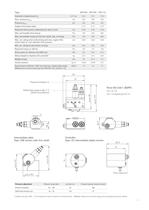
Type SVH 062 SVH 092 Geometric displacement Vg cm3 /rev. 62.4 87.2 SVH 112 110.4 Nom. pressure pnom bar 350 350 350 Pressure pmax bar 400 400 400 Angle of the swash plate 21.5° 21.5° 21.5° Required inlet pressure (absolute) for open circuit bar 0.85 0.85 0.85 Max. permissible drive torque Nm 430 530 600 Max. permissible torque for the thru-shaft, dep. on flange Nm 100 530 600 Max. rev. rating when self priming and max. angle of the swash plate at 1 bar absolute inlet pressure rpm 2500 2300 2200 Min. rev. rating for permanent running rpm 500 500 500 Required torque at 100 bar Nm 100 151 184 Drive...
Open the catalog to page 3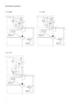
Controller symbols Coding LSNR Coding .../ZL 4 Coding NR
Open the catalog to page 4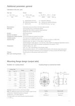
Additional parameter, general Calculation of the nom. sizes: Flow rate Vg x n x ηv Q = (lpm) 1000 Torque Power 1,59 x Vg x ∆p M = (Nm) 100 x ηmh 2π x M x n Mxn Q x ∆p P = = = 60000 9549 600 x ηt Vg Displacement (cm³/rev.) ∆p Differential pressure (bar) n Speed (rpm) ηv = Volumetric efficiency ηmh = Mechanical-hydraulic efficiency ηt = Total efficiency (ηt = ηv x ηmh) Nomenclature Mounting Surface Direction of rotation Changing the rotation direction Installed position Hydraulic fluid Temperature Filtration Max. perm. housing pressure Axial piston pump according to the swash plate principle At...
Open the catalog to page 5
Curves Flow and Power Charts show flow/pressure (without controller). Power at max. setting angle and power at min.setting angle and 1500 rpm P owe r ( 06 SVH 6 2 12 2) SVH 1 12) r (1 we ) Po 0 92 er ( ow P 2) Inlet pressure (bar) Delivery flow (06 Power (kW) Delivery flow (l/min) Delivery flow (092) SVH 9 2 Inlet pressure (LSNR-controller) Graph valid at viscosity 75 mm2/s at max. setting angle. Delivery flow (112) (1 abs.) Speed (rpm) Pressure (bar) Controller curve Response time T1 (LSNR-controller) Delivery flow Q (%) Response time T1 (ms) Coding L Pressure / Delivery flow Pressure (bar)...
Open the catalog to page 6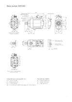
Basic pumps: SVH 062 Mounting flange design (input side) coding Y ISO 7653-1985 Stroke limitation Splined shaft coding D conforming DIN ISO 14 Rotation direction, clockwise (facing the input shaft) Max. torque 110 Nm (4 x tie rod M12x170) Stroke limitation (Vg approx. 4 cm3 /rev.) Rotation direction, counter clockwise (facing the input shaft) Coding UNF ports conforming SAE J 514: P = 1 5/16-12 UN-2B S = Flange, suction port D = 1 1/16-12 UN-2B LS = G 1/4 (ISO 228/1 (BSPP)) with adaptor for 7/16-20 (SAE-4) Ports (ISO 228/1 (BSPP)): P = Pressure outlet G 3/4 S = Flange, suction port D = Case drain...
Open the catalog to page 7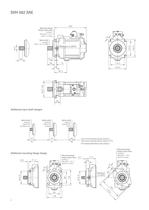
SVH 062 SAE Mounting flange design (input side) coding F ISO 3019-1 127-4 (SAE C-4-Hole) Spline shaft coding S SAE C 14T 12/24DP Bleeding G 1/8 (BSPP) Additional input shaft designs Spline shaft coding U SAE B 13T 16/32DP short Spline shaft coding H SAE B 13T 16/32DP Spline shaft coding T SAE BB 15T 16/32 (with mounting flange design coding Y) (with mounting flange design coding F, Z, X) For missing dimensions, see coding Y Additional mounting flange design Mounting flange design (input side) coding X ISO 3019-1 101-2 (SAE B-2-Hole) Mounting flange design (input side) coding Z ISO 3019-1 101-4...
Open the catalog to page 8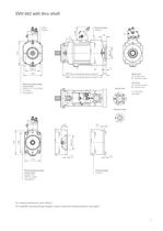
SVH 062 with thru-shaft 2xM10, 16 deep Housing design Coding 2 (mounting flange design coding Y) Right hand A Suction port B Pressure outlet (mounting flange design coding F, Z, X) Mounting flange design (output side) coding C 011, C 012 (SAE A-2-Hole), (see page 5) Suction port Left hand A Pressure outlet B Suction port For port sizes, see page 7 Pressure outlet Mounting flange design (output side) coding C 014 (SAE B-2-Hole) (see page 5) Housing design Coding 3 For missing dimensions, see coding Y For available mounting flange designs (output side) and coupling sleeves, see page 5 9
Open the catalog to page 9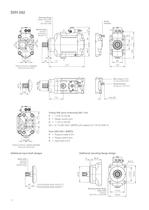
SVH 092 Mounting flange design (input side) coding Y ISO 7653-1985 Stroke limitation Splined shaft coding D conforming DIN ISO 14 Rotation direction, clockwise (facing the input shaft) Max. torque 150 Nm (4 x tie rod M14x190) Stroke limitation (Vg approx. 5 cm3 /rev.) Coding UNF ports conforming SAE J 514: P = 1 5/16-12 UN-2B S = Flange, suction port D = 1 1/16-12 UN-2B LS = G 1/4 (ISO 228/1 (BSPP)) with adaptor for 7/16-20 (SAE-4) Ports (ISO 228/1 (BSPP)): P = Pressure outlet G 3/4 S = Flange, suction port D = Case drain G 3/4 Rotation direction, counter clockwise (facing the input shaft) Additional...
Open the catalog to page 10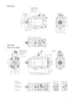
SVH 092 Mounting flange design (input side) coding F ISO 3019-1 127-4 (SAE C-4-Hole) Spline shaft coding S 14T-12/24 DP (SAE C) Bleeding G 1/8 (BSPP) SVH 092 with thru-shaft Mounting flange design (output side) coding C 021, C 022 (SAE A-2-Loch) (see page 5) Stroke limitation M10, 15 deep (mounting flange design coding Y) (mounting flange design coding F, Z, X) Right hand A Suction port B Pressure outlet Suction port Pressure outlet Left hand A Pressure outlet B Suction port For port sizes, see page 10 11
Open the catalog to page 11All Sunfab Hydraulics catalogs and technical brochures
 Flushing Valve
2 Pages
 Speed Sensor
4 Pages
 DIODE GATE
2 Pages
 INJECTOR
2 Pages
 SAM 010-130 DIN
7 Pages
 SVH 130
20 Pages
 SCM 012-130 DIN
7 Pages
 SCM 010-130 SAE
12 Pages
 SCM 010-130 ISO
12 Pages
 SAP 084, 108 DIN Optimised
4 Pages
 SAPT 090, 130 DIN
4 Pages
 SAP 012-108 DIN
4 Pages
 SCPD 76/76 DIN
4 Pages
 SLPD 40/20-64/32 SAE
4 Pages
 SLPD 20/20-64/32 DIN SAVTEC
5 Pages
 SLPD 20/20-64/32 DIN
4 Pages
 SCPD 56/26 DIN By-Pass
4 Pages
 SCPD 56/26 DIN
4 Pages
 SCM 025-108 M2
8 Pages
 SCM 012-130 SAE
12 Pages
 SCPT 090, 130 DIN
4 Pages
 SCP 012-130 ISO
7 Pages
 SCP 084, 108 DIN Optimised
4 Pages
 SAP 040-064 DIN
4 Pages
 SCP 012-108 DIN
4 Pages
 Accessories Catalog
28 Pages
 Product Catalogue
25 Pages
 axial piston hydraulic motor SAE
11 Pages
 Splitter gearbox SZ 121
2 Pages
 SVH 062, 092, 112
16 Pages
 SC 5012-5108 SAE
2 Pages
 SC 012-108 DIN
2 Pages
 suction oil filter
2 Pages
 hydraulic relief valve
2 Pages
 oil tank
2 Pages
 power take-off for engine
2 Pages
 dual shaft gearbox
2 Pages
 hydraulic truck pump
2 Pages
 SCM 047-090 M2
6 Pages


Archived catalogs
 Anti-Cavitation Valve_2012
2 Pages
 ANTI-CAVITATION VALVE_2015
2 Pages
 axial piston hydraulic motor
10 Pages


- Bourn And Koch valve
- Flap valve
- Check valve
- Hydraulic pump
- Hydraulic valve
- Gear train gear reducer
- Compact valve
- Shaft gearhead
- Helical gear gearhead
- Hydraulic piston pump
- Relief valve
- Clamp gearbox
- Miniature valve
- Hydraulic motor
- Hydraulic gear pump
- Compact hydraulic pump
- Pump valve
- Magnetic speed sensor
- Rotational speed sensor
- Pilot-operated relief valve