- Catalogs
- Sunfab Hydraulics
- SVH 130
SVH 130
1 /20Pages

SVH 130
1 /20Pages
Catalog excerpts

The Sunfab variable displacement pump with its rugged construction is designed for direct mounting at the auxiliary drive (P.T.O.) of commercial vehicles. Sunfab SVH is rotation-direction dependent and should be ordered in either right-hand or left-hand designs. With a max. displacement of 130 cm3/rev. and a peak pressure of 450 bar it is suited for many applications. This is complemented by the high self priming rate and the low noise level. The pump delivery flow is dependent on the present drive speed and geometric displacement. The flow is adjust ble in a range between 0 and Qmax. a Other advantages of Sunfab SVH: • • • • • Long service life is ensured due to the pressurized lubrica- • tion of the swash plate bearing shell. • Short reaction time when resetting the flow Compact installation dimensions High pressure Externally drained for best cooling Rugged construction and long service life Low noise emission High power-to-weight-ratio 3114GB1601 Rev 1.3 - PAGE 1/20 Sunfab Hydraulics AB, Box 1094, SE-824 12 Hudiksvall, Sweden. Tel: +46 650-367 00, Fax: +46 650-367 27, E-mail: [email protected] Web: ww
Open the catalog to page 1
Versions, main data SVH - 092 R DZN - 2 - LSNR/ZL - 2/65 - 350 - C 022 Basic type Mounting flange design Nominal size no coding = Ports conforming ISO 228/1 (BSPP) UNF = Ports conforming SAE J 514 (output side), see page 5 Pressure specification (bar) Direction of rotation: L = Left-hand (counter clockwise) R = Right-hand (clockwise) always facing the drive shaft no coding = Without stroke limitation (standard) 2 = With stroke limitation (not available for versions with thru-shaft SVH 062, 092, 112) 2 /... = Factory set stroke limitation, specification Vg (cm2/rev.) Shaft design: D = Splined...
Open the catalog to page 2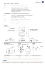
Description of the controllers LSNR Load-Sensing controller with integrated pressure limitation Pressure controller, adjustable directly at the pump. The Pressure controller automatically maintains a constant system pressure independant of the required flow. Therefore it is suited for constant pressure systems, where differing flow is required or as efficient pressure limitation of the hydraulic system Intermediate plates Intermediate plate only in combination with controllers LSNR or NR SVH 062, 092, 112: Intermediate plate with power controller (torque limitation) Product ”Pressure x Displacement”...
Open the catalog to page 3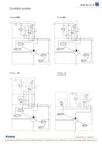
Controller symbols Coding LSNR 3114GB1601 Rev 1.3 - PAGE 4/20 Sunfab Hydraulics AB, Box 1094, SE-824 12 Hudiksvall, Sweden. Tel: +46 650-367 00, Fax: +46 650-367 27, E-mail: [email protected] Web: www.sunfab.com
Open the catalog to page 4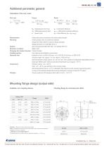
Additional parameter, general Calculation of the nom. sizes: Flow rate Vg x n x hv Q= (lpm) 1000 Vg Displacement (cm³/rev.) ∆p Differential pressure (bar) n Speed (rpm) Nomenclature Mounting Surface Direction of rotation Changing the rotation direction Installed position Hydraulic fluid Temperature Filtration Axial piston pump according to the swash plate principle At the auxiliary drive of commercial vehicles (flange ISO 7653-1985 for trucks)or flange assembly (flange ISO 3019-2 or SAE/ISO 3019-1) Gas nitrocarburized SVH 062, 092, 112. Painted SVH 130 Right or left Contact Sunfab Any (observe...
Open the catalog to page 5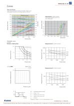
Curves Flow and Power Charts show flow/pressure (without controller). Power at max. setting angle and power at min.setting angle and 1500 rpm Delivery flow (130) Inlet pressure (LSNR-controller) Graph valid at viscosity 75 mm2/s at max. setting angle. Abbildung 6: p Druck (bar); Q Förderstrom (l/m 1. Förderstrom Leistung Leistung (Nullhub) Delivery flow (l/min) (1 abs.) Power (zero stroke) Abbildung 6: p Druck (bar); Q Förderstrom (l/min) Abbildung Controller curve 6: p Druck (bar); Q Förderstrom (l/min) 1. 2. 3. Förderstrom Coding L 1. Pressure Delivery flow Leistung / Förderstrom 2. Leistung...
Open the catalog to page 6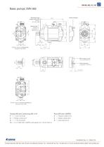
Mounting flange design (input side] Splined shaft Rotation direction, clockwise [R] [facing the input shaft) Stroke limitation Stroke limitation Coding UNF ports conforming SAE J 514: Ports (ISO 228/1 (BSPPTJ: S = Flange, suction port S = Flange, suction port LS = G 1/4 [ISO 228/1 [BSPPJ] with adaptor for 7/16-20 [SAE-4J Sunfab Hydraulics AB, Box 1094, SE-824 12 Hudiksvall, Sweden. Tel: +46 650-367 00, Fax: +46 650-367 27, E-mail: [email protected] Web: www.sunfab.com
Open the catalog to page 7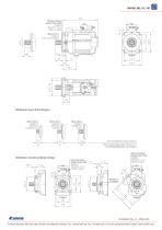
Mounting flange design (input side) coding F ISO 3019-1 127-4 (SAE C-4-Hole) Spline shaft coding S SAE C 14T 12/24DP Additional input shaft designs Spline shaft coding U SAE B 13T 16/32DP short Spline shaft coding H SAE B 13T 16/32DP Spline shaft coding T SAE BB 15T 16/32 (with mounting flange design coding Y) (with mounting flange design coding F, Z, X) For missing dimensions, see coding Y Additional mounting flange design Mounting flange design (input side) coding X ISO 3019-1 101-2 (SAE B-2-Hole) Mounting flange design (input side) coding Z ISO 3019-1 101-4 (SAE B-4-Hole) 3114GB1601 Rev 1.3...
Open the catalog to page 8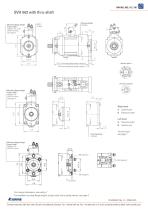
SVH 062 with thru-shaft Housing design Coding 2 Mounting flange design (output side) coding C 011, C 012 (SAE A-2-Hole), (see page 5) (mounting flange design coding Y) (mounting flange design coding F, Z, X) Mounting flange design (output side) coding C 014 (SAE B-2-Hole) (see page 5) Flanschausführung (abtriebsseitig) Kennzeichen C 015 (SAE B-4-Loch) Right hand A Suction port B Pressure outlet Left hand A Pressure outlet B Suction port Flanschausführung (abtriebsseitig) Kennzeichen C 015 (SAE B-4-Loch) Housing design Coding 3 For port sizes, see page 7 Mounting flange design (output side) coding...
Open the catalog to page 9
SVH 092 Mounting flange design (input side) coding Y ISO 7653-1985 Stroke limitation Splined shaft coding D conforming DIN ISO 14 Rotation direction, clockwise (R) (facing the input shaft) Max. torque 150 Nm (4 x tie rod M14x190) Stroke limitation (Vg approx. 5 cm3 /rev.) Coding UNF ports conforming SAE J 514: P = 1 5/16-12 UN-2B S = Flange, suction port D = 1 1/16-12 UN-2B LS = G 1/4 (ISO 228/1 (BSPP)) with adaptor for 7/16-20 (SAE-4) Ports (ISO 228/1 (BSPP)): P = Pressure outlet G1 S = Flange, suction port D = Case drain G 3/4 Rotation direction, counter clockwise (L) (facing the input shaft)...
Open the catalog to page 10All Sunfab Hydraulics catalogs and technical brochures
 Flushing Valve
2 Pages
 Speed Sensor
4 Pages
 DIODE GATE
2 Pages
 INJECTOR
2 Pages
 SAM 010-130 DIN
7 Pages
 SCM 012-130 DIN
7 Pages
 SCM 010-130 SAE
12 Pages
 SCM 010-130 ISO
12 Pages
 SAP 084, 108 DIN Optimised
4 Pages
 SAPT 090, 130 DIN
4 Pages
 SAP 012-108 DIN
4 Pages
 SCPD 76/76 DIN
4 Pages
 SLPD 40/20-64/32 SAE
4 Pages
 SLPD 20/20-64/32 DIN SAVTEC
5 Pages
 SLPD 20/20-64/32 DIN
4 Pages
 SCPD 56/26 DIN By-Pass
4 Pages
 SCPD 56/26 DIN
4 Pages
 SCM 025-108 M2
8 Pages
 SCM 012-130 SAE
12 Pages
 SCPT 090, 130 DIN
4 Pages
 SCP 012-130 ISO
7 Pages
 SCP 084, 108 DIN Optimised
4 Pages
 SAP 040-064 DIN
4 Pages
 SCP 012-108 DIN
4 Pages
 Accessories Catalog
28 Pages
 Product Catalogue
25 Pages
 axial piston hydraulic motor SAE
11 Pages
 Splitter gearbox SZ 121
2 Pages
 SVH 062, 092, 112
16 Pages
 SC 5012-5108 SAE
2 Pages
 SC 012-108 DIN
2 Pages
 suction oil filter
2 Pages
 hydraulic relief valve
2 Pages
 oil tank
2 Pages
 power take-off for engine
2 Pages
 dual shaft gearbox
2 Pages
 variable flow hydraulic pump
16 Pages
 hydraulic truck pump
2 Pages
 SCM 047-090 M2
6 Pages


Archived catalogs
 Anti-Cavitation Valve_2012
2 Pages
 ANTI-CAVITATION VALVE_2015
2 Pages
 axial piston hydraulic motor
10 Pages


- Bourn And Koch valve
- Flap valve
- Check valve
- Hydraulic pump
- Hydraulic valve
- Gear train gear reducer
- Compact valve
- Shaft gearhead
- Helical gear gearhead
- Hydraulic piston pump
- Relief valve
- Clamp gearbox
- Miniature valve
- Hydraulic motor
- Hydraulic gear pump
- Compact hydraulic pump
- Pump valve
- Magnetic speed sensor
- Rotational speed sensor
- Pilot-operated relief valve