Catalog excerpts
IPC-A-600H-2010 Acceptability of Printed Boards April 2010 Supersedes IPC-A-600G July 2004 Association Connecting Electronics Industries
Open the catalog to page 1
In May 1995 the IPC’s Technical Activities Executive Committee (TAEC) adopted Principles of Standardization as a guiding principle of IPC’s standardization efforts. Standards Should: • Show relationship to Design for Manufacturability (DFM) and Design for the Environment (DFE) • Minimize time to market • Contain simple (simplified) language • Just include spec information • Focus on end product performance • Include a feedback system on use and problems for future improvement Standards Should Not: • Inhibit innovation • Increase time-to-market • Keep people out • Increase cycle time • Tell...
Open the catalog to page 2
Acceptability of Printed Boards Developed by the IPC-A-600 Task Group (7-31a) of the Product Assurance Committee (7-30) of IPC Users of this publication are encouraged to participate in the development of future revisions. Contact: IPC 3000 Lakeside Drive, Suite 309S Bannockburn, Illinois 60015-1249 Tel 847 615.7100 Fax 847 615.7105
Open the catalog to page 3
Acknowledgment Any standard involving a complex technology draws material from a vast number of sources. While the principal members of the A-600 Task Group (7-31a) of the Product Assurance Committee (7-30) are shown below, it is not possible to include all of those who assisted in the evolution of this standard. To each of them, the members of IPC extend their gratitude. Special thanks goes to the members of the Rigid Printed Board Committee (D-30) for their efforts in establishing acceptance criteria for printed boards. Product Assurance Committee Chair Mel Parrish STI Electronics...
Open the catalog to page 4
This document describes the preferred, acceptable, and nonconforming conditions that are either externally or internally observable on printed boards. It represents the visual interpretation of minimum requirements set forth in various printed board specifications, e.g.; IPC-6010 series, J-STD-003, etc. 1.2 PURPOSE The visual illustrations in this document portray specific criteria of the requirements of current IPC specifications. In order to properly apply and use the content of this document, the printed board should comply with the design requirements of the applicable IPC-2220 series...
Open the catalog to page 7
Introduction (cont.) Acceptability criteria in this document have been separated so that printed board product may be evaluated to any one of the three classes. The use of one class for a specific characteristic does not mean that all other characteristics must meet the same class. Selection should be based on minimum need. The customer has the ultimate responsibility for identifying the class to which the product is evaluated. Thus, accept and/or reject decisions must be based on applicable documentation such as contracts, procurement documentation, specifications, standards and reference...
Open the catalog to page 8
Introduction (cont.) magnifications and devices with reticles or scales in the instrument, which allow accurate measurements of the specified dimensions. Contract or specification may require other magnifications. Plated-through holes (PTHs) shall be internally examined for foil and plating integrity at a magnification of 100X. Referee examinations shall be accomplished at a magnification of 200X. Automated Inspection Technology (AIT) results may be applicable to the evaluation of many of the dimensional characteristics illustrated in this document. 1.6 Applicable Documents The following...
Open the catalog to page 9
2 EXTERNALLY OBSERVABLE CHARACTERISTICS Introduction This section addresses those characteristics which are observable from the surface. This includes those characteristics that are external and internal in the printed board but visible from the surface as follows: • Surface Imperfections such as burrs, nicks, scratches, gouges, cut fibers, weave exposure and voids. • Subsurface Imperfections such as foreign inclusions, measling/crazing, delamination, pink ring and laminate voids. • Imperfections in Conductive Pattern such as loss of adhesion, reduction of conductor width or thickness due...
Open the catalog to page 10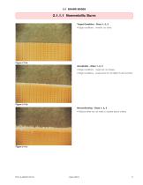
2.1.1.1 Nonmetallic Burrs Target Condition - Class 1, 2, 3 • Edge conditions - smooth, no burrs. • Edge conditions - rough but not frayed. • Edge conditions - loose burrs do not affect fit and function. • Defects either do not meet or exceed above criteria.
Open the catalog to page 11
2.1.1.2 Metallic Burrs Target Condition/Acceptable - Class 1, 2, 3 • Edges shall be clean cut and without metallic burrs. • Defects either do not meet or exceed above criteria. April 2010 标准分享网 www.bzfxw.com 免费下
Open the catalog to page 12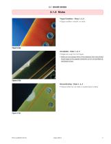
2.1.2 Nicks Target Condition - Class 1, 2, 3 • Edge condition -smooth, no nicks. • Edges are rough but not frayed. • Nicks do not exceed 50% of the distance from the printed board edge to the nearest conductor or 2.5 mm [0.0984 in], whichever is less. • Defects either do not meet or exceed above criteria.
Open the catalog to page 13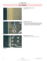
2.1.3 Haloing Target Condition - Class 1, 2, 3 • Distance between the haloing penetration and the nearest conductive feature is not less than the minimum lateral conductor spacing, or 100 µm [3,937 µin] if not specified. • Defects either do not meet or exceed above criteria. April 2010 标准分享网 www.bzfxw.com 免费
Open the catalog to page 14
2.2 BASE MATERIAL SURFACE Introduction Identification of Imperfections Nondestructive visual criteria have been established to aid in the identification and disposition of laminate defects. Refer to the following sections where definitions, illustrations and photographs have been provided which precisely define and identify the following conditions: Surface 2.2 • weave exposure • weave texture • exposed/disrupted fibers • foreign inclusions It is important to note that laminate defect conditions may exist when the fabricator receives the material from the laminator, or may become apparent...
Open the catalog to page 15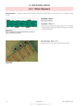
2.2 BASE MATERIAL SURFACE 2.2.1 Weave Exposure Weave Exposure: A surface condition of base material in which the unbroken fibers of woven cloth are not completely covered by resin. Acceptable - Class 3 • No weave exposure. Acceptable - Class 1, 2 • Excluding the area(s) with weave exposure, the remaining space between conductors meets the minimum conductor spacing requirement. Figure 221a Note: This graphic is for illustrative purposes only and does not require a microsection evaluation. • Defects either do not meet or exceed above criteria. April 2010 标准分享网 www.bzfxw.com 免费
Open the catalog to page 16
