- Catalogs
- SUMITOMO (SHI) Cyclo Drive Germany GmbH
- Taper Grip® Bushing Installation Guide
Taper Grip® Bushing Installation Guide
1 /4Pages

Taper Grip® Bushing Installation Guide
1 /4Pages
Catalog excerpts
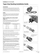
Taper Grip® Bushing Installation Guide Introduction The keyless Taper-Grip® bushing system provides simple and reliable shaft attachment for Sumitomo Speed reducers and gearmotors. This system allows bi-directional shaft rotation and stop-start operation with a powerful, slip-free grip. To assure peak performance of your equipment, please read, understand and follow these installation instructions. Safety Disconnect all power sources from the equipment before beginning this installation procedure. Handle the components with care and avoid all sharp or machined edges to prevent personal injury or damage to the components. Fig. 1 Taper-Grip® Bushing Parts Before Installing Unit on Driven Shaft (Steps 1-7) Carefully inspect the driven equipment shaft. Remove all burrs, corrosion, lubricants, and foreign matter from the shaft surface. Verify the shaft diameter is within the dimensional tolerances shown in Table 1. Table 1 Driven Shaft Tolerances Shaft Diameter (inches) 3/4” – 1-1/8” 1-3/16” – 2” 2-1/16” – 3-1/8” 3-3/16” – 4-3/4” 4-13/16” – 6-1/2” Fig. 2 Remove Safety Cover Clean all surfaces of the shaft, the bushing, the thrust collar and the unit bore with solvent to remove all grease and oil. Step 1 – Remove the Taper-Grip® bushing safety cover (see Fig. 2). Fig. 3 Slide Thrust Collar on Bushing Step 2 – Remove the cap screws from the bushing. Lightly oil the threads of the cap screws and partially re-insert them into the threaded holes in the bushing flange. The ends of the cap screws should not extend beyond the rear face of the bushing flange. Apply thin layer of anti-seize paste to male threads of bushing only. Step 3 – Slide the thrust collar onto the Taper-Grip® bushing (see Fig. 3). Step 4 – Apply a thin layer of anti-seize paste to the male threads of the Taper-Grip® Bushing only (see Fig.4). Based on tests, Sumitomo recommends Bostik Never-Seez Regular Grade or equivalent. Ensure that anti-seize paste does not enter the Taper-Grip® Bushing bore. Caution: Do not apply anti-seize paste to the female threads in the hub. Fig. 4 Apply Anti-seize Paste Step 5 – Carefully thread the Taper-Grip® bushing into the hub of the speed reducer or gearmotor until the thrust collar solidly engages the unit hub surface and the bushing flange (see Fig. 5). Caution: Do not cross-thread. Bushing should thread easily into hub. Step 6 – Unscrew the Taper-Grip® bushing to create a 1mm (0.04”) gap between the thrust collar and the bushing flange. Step 7 – Hand-tighten the cap screws until they firmly press the thrust collar against the unit hub surface. The unit is ready for installation on the driven shaft. www.sumito
Open the catalog to page 1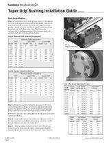
Unit Installation Step 8 - Position unit with the bushing flange located on the outboard side of the unit. Align the bushing with the driven shaft. Slide the unit onto the driven shaft as close to the driven shaft support bearing as possible. Ideally, the driven shaft should extend beyond the bushing flange face (see Fig. 7). Refer to Fig. 6 and Table 2 below for minimum shaft to bushing engagement. For maximum depth to the end of the shaft, refer to Fig. 6 and Table 3 below. Table 2 Minimum Shaft to Bushing Engagement Minimum Shaft Engagement HSM Cyclo® HBB Cyclo® BBB4 Model mm in. Model mm...
Open the catalog to page 2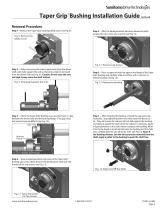
Taper Grip® Bushing Installation Guide Removal Procedure Step 1 – Remove the Taper-Grip® bushing safety cover (see Fig. 8). Fig. 8 Remove the Safety Cover Step 5 – After the liquid penetrant has been allowed to settle, remove the cap screws one at a time (see Fig 12). Fig. 12 Remove Cap Screws Step 2 – Before removing the reducer/gearmotor from the driven shaft, externally support the unit so that all its weight is removed from the driven shaft (see Fig. 9). Caution: Do not raise the unit too high. It may cause the shaft to bind. Fig. 9 Externally Support the Unit Step 3 – Check the Taper-Grip®...
Open the catalog to page 3
Sumitomo Machinery Corporation of America Headquarters & Manufacturing 4200 Holland Boulevard Chesapeake, VA 23323 Tel: 757-485-3355 • Fax: 757-485-7490 www.sumitomodrive.com E-mail: [email protected] www.sumitomodrive.com World Headquarters Japan Sumitomo Heavy Industries, Ltd. Power Transmission & Controls Group ThinkPark Tower, 1-1, Osaki 2-chome, Shinagawa-ku, Tokyo 141-6025 Japan Tel: +81-36-737-2511 • Fax: +81-36-866-5160 For worldwide locations, please visit www.sumitomodrive.com/worldwide ♦ Sumitomo Machinery Corporation of America Manual 19.001.61.008; Supersedes Manual 19.001.61.007...
Open the catalog to page 4All SUMITOMO (SHI) Cyclo Drive Germany GmbH catalogs and technical brochures
 Paramax 9000 series
281 Pages
 Helical Shaft Mount (HSM)
58 Pages
 Bevel Buddybox 4
60 Pages
 SERVO 6000
38 Pages
 Motion Control DrivesE CYCLO
28 Pages
 BEVEL BUDDYBOX 4
248 Pages
 Cyclo® BBB5
270 Pages
 Fine Cyclo®
123 Pages
 PARAMAX ® 9000 Series
281 Pages
 Fine Cyclo UA Brochure
2 Pages
 Fine Cyclo Flyer
2 Pages
 Precision Drives Product Catalog
20 Pages
 Fine Cyclo F4CF – UA 25
2 Pages
 Fine Cyclo F4CFS–UA 115
4 Pages
 Fine Cyclo F4C–C 25
4 Pages
 Paramax 9000
352 Pages
 Neo Hyponic
120 Pages
 Servo 100
58 Pages
 IB Series catalogues
94 Pages
 Servo 6000 series
6 Pages
 Cyclo® Drive 6000
139 Pages
 Paramax® 9000
352 Pages
 HSM series
58 Pages
 Astero series
186 Pages
 Servo Planetary Gears EPG
6 Pages
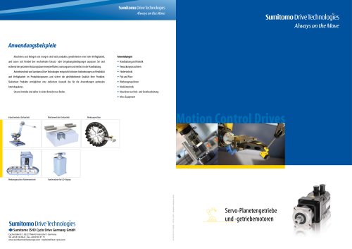 Servo-Planetary Gears
4 Pages
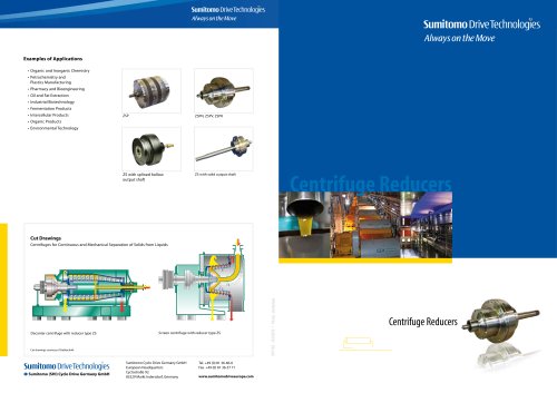 Centrifuge reducers
2 Pages
 Fine Cyclo®
114 Pages


Archived catalogs
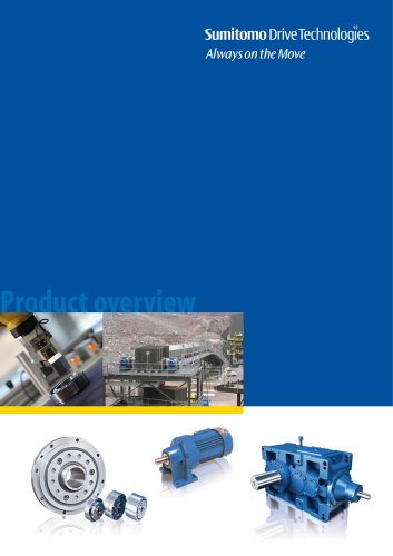 Product overview
16 Pages
- Actuator
- Electric gearmotor
- Electric actuator
- Planetary gearbox
- Coaxial gearhead
- Precision gearhead
- Direct current gear-motor
- Right angle gearhead
- Compact gearhead
- Solid-shaft gearhead
- Gear train gear reducer
- Hollow-shaft gearhead
- Gearbox for industrial applications
- Transmission gearhead
- Right angle electric gearmotor
- Industrial electric gearmotor
- Multi-stage gearhead
- Shaft gearhead
- Single-stage gearhead
- Coaxial gearmotor