

Servo 100

Servo 100
The document is a technical catalog from Sumitomo (SHI) Cyclo Drive Germany GmbH, focusing on the SERVO 100 and SERVO 6000 series gearboxes. These are designed for precision motion control and medium positioning control, respectively.
The gearboxes are constructed from aluminum, offering low weight and reduced backlash. The SERVO 100 is optimized for precise motion control, while the SERVO 6000 is suited for medium positioning tasks.
- Low backlash
- High shock load capacity
- High efficiency
- Compact size
- Low noise
- Long lifetime
- Maintenance-free
- Flexible mounting options
- Cost-effective
- Conveyors
- Material handling systems
- Printing machines
- Machine tools
- Robotic systems
- Packaging machines
- Textile machines
The Cyclo gearbox uses an eccentric bearing to drive cycloid discs within a ring gear housing, resulting in reverse rotation at reduced speed, transmitted to the output shaft via pins and rollers.
The document details the selection process for gearbox size based on load duty cycle, axial and radial loads, and torque requirements, including tables and formulas for calculations.
The SERVO 100 series offers four sizes with output torques from 25 Nm to 500 Nm and reduction ratios from 11:1 to 87:1. They are compact, lightweight, and compatible with standard AC/DC servomotors.
Instructions for motor mounting and coupling methods are provided, emphasizing dry, grease-free motor shafts and correct application of couplings to avoid damage.
DIN standards for motor flange concentricity and squareness tolerances are referenced, with guidelines for radial and axial loads on shafts and correction factors for coupling methods.
Gearboxes are pre-lubricated for life, with grease renewal recommended after 20,000 hours or five years. Disassembly is discouraged due to specific settings and seals.
Tables provide data on allowable loads, coupling factors, and dimensions for the SERVO 100 series, crucial for component selection and application compatibility.
Installation and maintenance procedures emphasize dry, grease-free components, correct torque for locking ring screws, and heating components to 100°C for fitting.
Speed reducers can be mounted in any position, designed for flange mounting, and are grease-lubricated for life, requiring lubricant changes only after 20,000 hours or 5 years.
The SERVO 6000 series offers high shock load capacity, compact size, high efficiency, low noise, maintenance-free operation, long life, and unlimited mounting flexibility.
Specifications include reduction ratios, allowable input power, and output torque for various frame sizes, with a maximum allowable input speed of 4000 min-1 at a 50% duty cycle.
Dimensions for different mounting forms and nomenclature for shaft positions are provided, with tables according to DIN ISO standards.
Detailed specifications for the SERVO 6000 series include dimensions for various frame sizes and components, with tables for measurements and mass data.
Assembly instructions for the SERVO 6000 with a servo motor include applying grease, ensuring proper alignment, and careful bolt tightening.
Correct grease type and maintenance within specified temperature ranges are emphasized, with grease replacement recommended after 20,000 hours or 4-5 years.
Tables provide data on dimensions, mass, and inertia for different frame sizes, with correction factors for radial and axial loads detailed.
Proper alignment during assembly is crucial to prevent damage. Use specified grease types and adhere to maintenance schedules for optimal performance and longevity of the SERVO 6000 units.
Catalog excerpts

Sumitomo DriveTechnologies Compact low backlash gearboxes Kompakte spielreduzierte Getriebe
Open the catalog to page 1
Copyright Sumitomo (SHI) Cyclo Drive Germany GmbH 2010. All rights reserved. Reproduction in part or whole is not permitted without our prior approval. Whilst every care has been taken in preparation of this catalogue, no liability can be accepted for any errors or omissions. Modifications reserved. Copyright Sumitomo (SHI) Cyclo Drive Germany GmbH 2010. Alle Rechte vorbehalten. Nachdruck, auch auszugsweise, nur mit unserer Genehmigung gestattet. Die Angaben in diesem Katalog wurden mit größter Sorgfalt auf ihre Richtigkeit überprüft. Trotzdem kann für eventuell fehlerhafte oder unvollständige...
Open the catalog to page 2
SERVO Product description The SERVO Precision Gears Series are compact speed reducers with low backlash, made in aluminium and ideal for all low weight applications. SERVO Getriebe sind spielreduzierte Getriebe in Aluminiumausführung und ideal für alle Applikationen mit geringem Gewicht. The SERVO 100 is custom made for Motion Precision Control, the SERVO 6000 range is recommended for Medium Positioning Control. SERVO 100 ist ein spielreduziertes Getriebe für Positioniersteuerung. SERVO 6000 wird für mittlere Positioniersteuerung empfohlen. Features & Benefits Eigenschaften & Vorteile Low backlash...
Open the catalog to page 3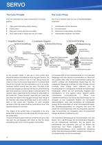
There are essentially four major components in the Cyclo 1. High speed shaft with eccentric bearing 3. Ring gear housing with pins and rollers 4. Slow speed shaft or flange with pins and rollers Das CYCLO-Getriebe setzt sich aus 4 Hauptbestandteilen 3. Bolzenring mit den Bolzen und Rollen 4. Abtriebswelle mit Bolzen und Rollen 1.Simplified System/ 2.Schematic Diagram 3.Sectional Drawing System-Darstellung Schema-Zeichnung ^^^^ Schnittzeichnung Pins & Rollers Mitnehmerbolzen & Rollen High Speed Shaft Cycloidal Disc/Kurvenscheibe Bearing / Walzkorper Slow Speed Shaft High Speed Shaft Antriebswelle...
Open the catalog to page 5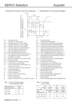
SERVO Selection 1. Determine the working cycle of the application 1. Arbeitszyklus der Anwendung festlegen Output torque / Abtriebsdrehmoment (T2) Input Speed / Antriebsdrehzahl (n1) Start up frequency Einschalt Frequenz Factor Faktor = load duty cycle [%] = axial load on output shaft [N] = allowable axial load on output shaft [N] = equivalent radial load on output shaft [N] 2zul = allowable radial load on output shaft[N] R = mean input speed during acceleration [min-1] n1A = mean input speed during braking [min-1] n1B = mean input speed during cycle [min-1] n1m n1m ED =mean input speed limited...
Open the catalog to page 7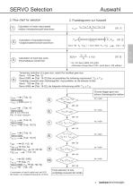
SERVO Selection 2. Flow chart for selection 2. Flussdiagramm zur Auswahl If combination of axial & radial load, ask SCG. Bei Radial- und Axiallast Rucksprache mit SCG. Final selection of size endgultige Auswahl der GrolJe Choose bigger gear size hohere GetriebegroUe wahlen 7 Sumitomo Drive Technologies
Open the catalog to page 8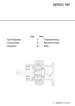
Type Designation Torque Ratings Page Seite g Sumitomo Drive Technologies
Open the catalog to page 10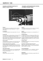
SERVO 100 Compact Low Backlash Gearboxes for Medium Precision Control Kompaktes verdrehspielreduziertes Getriebe für Medium Precision Control Selection Four mounting sizes are available from 25 Nm to 500 Nm rated output torque with ratios ranging from 11:1 to 87:1 (single stage) Auswahl 4 Baugrößen von 25 Nm bis 500 Nm stehen zur Auswahl, mit einstufigen Übersetzungen von 11:1 bis 87:1. Low Backlash The mechanical backlash at slow speed shaft is <3 arc min. Spielarm Das mechanische Verdrehspiel an der Abtriebswelle ist < 3 Winkelminuten. Compact Size For similar torques, the outside diameter...
Open the catalog to page 11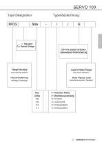
SERVO 100 Type Designation Size - = Standard S = Special Design Life time grease lubrication Lebensdauer-Fettschmierung Flange Mounting Code for Motor Flange Motor Flansch Code beliebige Einbaulage (siehe Motorauswahl-Tabellen) i = Reduction Ratios i = Übersetzung einstufig -
Open the catalog to page 12
SERVO 100 Torque ratings Einstufige Getriebe Mean input speed [min ] Rated output torque [Nm] Reduction ratio (single stage) mittlere Antriebsdrehzahl [min-1] Nennabtriebsdrehmoment [Nm] Übersetzung einstufig ** 20%ED / Duty factor *** Short time ** 20%ED / Lastfaktor *** kurzzeitig
Open the catalog to page 13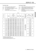
Technische Daten Mean input speed limited by ED [min-1] Max. allowable input speed [min-1] Max. output torque at emergency case [Nm] Max. acceleration torque [Nm] Reduction ratio Mass moment of inertia at input [kg cm2] mittlere Antriebsdrehzahl begrenzt durch ED [min-1] maximal zulässige Antriebsdrehzahl [min-1] zulässiges Drehmoment für NOT-AUS [Nm] maximales Beschleunigungsmoment [Nm] Übersetzung Massenträgheitsmoment [kg cm2] bezogen auf die Antriebswelle Applied torque on output shaft [Nm] An Abtriebswelle aufgebrachtes Moment [Nm] Approx. values (depending on motor shaft) Die Werte sind...
Open the catalog to page 14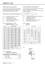
Radial load slow speed shaft When a gear or pulley is mounted on the slow speed shaft, a radial load is applied to the shaft. It is neces- sary to check the following formula to determine whether the shaft can accept the radial load. Equivalent radial load / aquivalente Radialbelastung FR2 zui= Allowable radial load of gearsize [N] Lf = Load location factor [Tab. 5b] Cf = Load correction factor [Tab. 6] d0 = Pitch diameter of gear or pulley [mm] n2m = Mean output speed [rpm] Radiale Belastung Abtriebswelle Wird die Abtriebswelle mit einem Ritzel oder einer Scheibe versehen, wirkt eine Kraft auf...
Open the catalog to page 15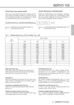
SERVO 100 Axial load slow speed shaft Axiale Belastung Abtriebswelle If the power is transmitted by bevel gear, spiral gear pinion or rigid coupling (for example in agitators), a complex axial/ radial load is applied to the shaft. In such applications we suggest you consult Sumitomo (SHI) Cyclo Drive Germany. Erfolgt die Kraftübertragung durch Kegelräder, schrägverzahnte Ritzel, starre Kupplung (z.B. bei Rührwerken), ergibt sich eine komplexe Belastung durch Axial-/ Radialkräfte. In diesen Fällen ist Rückfrage bei SDT erforderlich. Equivalent axial load FA2 / aquivalente axiale Belastung FA2...
Open the catalog to page 16All SUMITOMO (SHI) Cyclo Drive Germany GmbH catalogs and technical brochures
 Paramax 9000 series
281 Pages
 Helical Shaft Mount (HSM)
58 Pages
 Bevel Buddybox 4
60 Pages
 SERVO 6000
38 Pages
 Motion Control DrivesE CYCLO
28 Pages
 BEVEL BUDDYBOX 4
248 Pages
 Cyclo® BBB5
270 Pages
 Fine Cyclo®
123 Pages
 PARAMAX ® 9000 Series
281 Pages
 Fine Cyclo UA Brochure
2 Pages
 Fine Cyclo Flyer
2 Pages
 Precision Drives Product Catalog
20 Pages
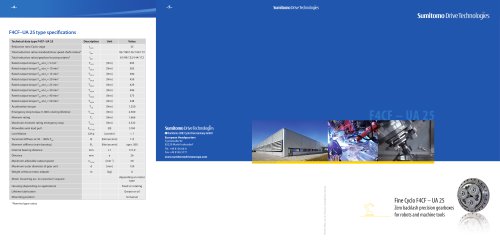 Fine Cyclo F4CF – UA 25
2 Pages
 Fine Cyclo F4CFS–UA 115
4 Pages
 Fine Cyclo F4C–C 25
4 Pages
 Paramax 9000
352 Pages
 Neo Hyponic
120 Pages
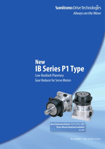 IB Series catalogues
94 Pages
 Servo 6000 series
6 Pages
 Cyclo® Drive 6000
139 Pages
 Paramax® 9000
352 Pages
 HSM series
58 Pages
 Astero series
186 Pages
 Servo Planetary Gears EPG
6 Pages
 Servo-Planetary Gears
4 Pages
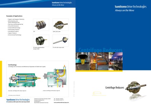 Centrifuge reducers
2 Pages
 Fine Cyclo®
114 Pages








Archived catalogs
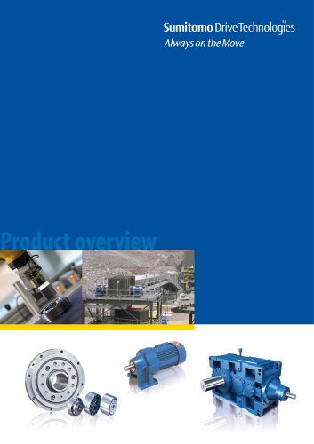 Product overview
16 Pages
- Actuator
- Electric gearmotor
- Planetary gearbox
- Electric actuator
- Coaxial gearhead
- Precision gearhead
- Right angle gearhead
- Direct current gear-motor
- Compact gearhead
- Solid-shaft gearhead
- Hollow-shaft gearhead
- Gear train gear reducer
- Gearbox for industrial applications
- Transmission gearhead
- Multi-stage gearhead
- Single-stage gearhead
- Industrial electric gearmotor
- Right angle electric gearmotor
- AC gear-motor
- Coaxial gearmotor