
- Catalogs
- SUMITOMO (SHI) Cyclo Drive Germany GmbH
- Motion Control DrivesE CYCLO

Motion Control DrivesE CYCLO
Motion Control DrivesE CYCLO
Sumitomo's E CYCLO High Precision Gearboxes, particularly the ECY series, are engineered for non-backlash applications. They integrate strain wave gear technology with CYCLO Drives' engagement theory, resulting in a compact and high-rigidity structure ideal for industrial robots and transfer devices.
Construction
The gearbox construction features components such as oil seals, main bearings, thrust plates, and eccentric high-speed shafts, ensuring durability and efficiency across various applications.
Features
The ECY series boasts high torque and rigidity, with a large diameter hollow shaft for optimal space utilization. It offers approximately 1.5 times the allowable peak torque compared to standard strain wave gears, enhancing safety and reducing assembly work.
Nomenclature
The nomenclature includes frame sizes (103, 105, 107) and reduction ratios (50, 80, 100), with symbols indicating series and specifications.
Line Up
All frame sizes support the full range of reduction ratios, allowing for versatile application.
Speed Ratio and Rotation Direction
The speed ratio and rotation direction are determined by the configuration of input, output, and fixed components, with specific formulas provided for each setup.
Standard Specifications
Specifications cover grease lubrication, ambient conditions, and mounting requirements, with gearboxes designed for indoor use in dust-free environments.
Operating Principle
The ECY series operates using a cycloid spline deformed into an elliptical shape, engaging with fixed and output ring gear housings to achieve rotation.
Rating
Ratings include torque specifications, allowable speeds, and moment of inertia, ensuring the gearboxes handle specific torque and speed conditions without overheating.
Engineering Data
Data includes angular transmission error, no-load friction torque, stiffness, hysteresis, and efficiency, with detailed tables for different frame sizes and reduction ratios.
Main Bearings
Specifications for main bearings ensure compatibility and performance in various applications.
High Speed Shaft Radial Load and Axial Load
Details on load capacities for high-speed shafts ensure proper application and longevity.
Selection
Guidelines for selecting the appropriate gearbox based on application requirements are provided.
Notice for Designing
Includes assembly methods, bolt tightening torque, lubrication, and other design considerations to ensure optimal performance.
Outline Drawing
Provides a visual representation of the gearbox design for reference.
Other
Includes warranty and safety precautions to ensure proper use and maintenance.
Specifications
Detailed specifications for roller bearings include parameters such as basic dynamic and static rated loads, allowable moments, radial and axial loads, and moment stiffness, with tables for different frame sizes and input speeds.
Procedures
Formulas for calculating radial and axial loads, as well as the life of the main bearing, are provided. Steps for evaluating load characteristics, input speed, and radial and axial loads on high-speed shafts are outlined, along with procedures for calculating average output and input speeds, and average load torque.
Standards and Recommendations
Tables for load factors, static safety factors, and coupling and shock factors are included. Recommendations for assembly methods, bolt tightening torque, and lubrication are provided, advising specific types of bolts and lubricants, and guidelines for assembly and maintenance.
Design Considerations
Design considerations ensure radial and axial loads do not exceed allowable values, and that the assembly method uses specific spigots for different parts. Guidelines for bolt tightening and lubrication intervals are also provided.
Warranty Information
The warranty period is specified as 18 months from delivery or 12 months from operation, whichever comes first. Conditions for warranty coverage and exclusions emphasize proper installation and maintenance.
Key Data from Tables and Figures
Tables provide values for allowable radial and axial loads at various input speeds, load position factors, coupling factors, and shock factors. Figures illustrate load patterns and assembly methods, while tables specify bolt sizes, tightening torques, and allowable transmission torques.
Catalog excerpts

Motion Control Drives E CYCLO High Precision Gearboxes ECY series
Open the catalog to page 1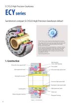
E CYCLO High Precision Gearboxes Sumitomo’s compact E CYCLO High Precision Gearboxes debut! CYCLO® Drives were created and developed by Sumitomo. This unique reducer structure by using teeth trochoid tooth profile* is being used in industrial robots and transfer devices all over the world. The ECY series, which was developed as a compact reducer for non-backlash applications, fuses the strain wave gear with the engagement theory of the CYCLO Drives, thus realizing high rigidity and a compact structure that were unavailable until now. * Epitrochoid parallel curves Main bearing (Cross roller bearing)...
Open the catalog to page 4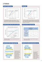
Allowable Peak Torque (N•m) General strain wave gear External dimensions (mm) The allowable peak torque is approximately 1.5 times (representative value) that of a general strain wave gear (equivalent size), enabling the device to be miniaturized. Ratcheting resistance (safety in the event of an overload) Tortional Stiffness (N•m/arc min) High rigidity Compact, and high torque Examples of general strain wave gear External gear Cup type / Hat type profile General strain wave gear Reasons for above-average strength The tortional stiffness is approximately twice (representative value) that of the...
Open the catalog to page 5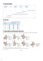
4. Line upTable 4-1 •: Production possible range Frame size [2] lnPut: High speed shaft ' 1-1 Output: Output ring gear housing Fixed: Ring gear housing i = -1/n High speed shaft Fixed: Ring gear housing i = -n , Input: Ring gear housing Output: High speed shaft Fixed: Output ring gear housing i = n + 1 Input: Output ring gear housing Output: Ring gear housing Fixed: High speed shaft i = n/(n + 1) [7] Input: Ring gear housing Output: Output ring gear housing Fixed: High speed shaft i = (n + 1)/n When the high speed shaft, ring gear housing and output ring gear housing all rotate, a combination...
Open the catalog to page 6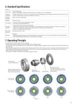
7. Operating Principle As a principle rule, the ECY series consists of 4 parts. • The bearing for eccentric deforms the cycloid spline into an elliptical shape. • The major axis of the cycloid spline that was deformed into an elliptical shape engages the fixed ring gear housing and the output ring gear housing. • When the fixed ring gear housing is fixed and the bearing used for the eccentric body is turned 1 rotation in the clockwise direction, the cycloid spline will rotate in the counterclockwise direction by an amount corresponding exactly to the difference in the number of teeth, while the...
Open the catalog to page 7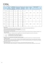
Table 8-1 Rating table 1. Rated torque The rated torque indicates the allowable output torque at the output flange at an input speed of 2000 r/min. 2. Allowable peak torque during acceleration and deceleration This is the peak torque allowed during normal acceleration and deceleration. 3. Allowable maximum momentary torque This is the allowable value of the impact torque that is applied instantaneously to the output shaft by an emergency shutdown or an external shock etc. Indicates the value when 104 deflection cycles are applied to the cycloid spline throughout the entire life of the product....
Open the catalog to page 8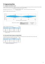
9. Engineering Data 9-1. Angular transmission error Angular transmission error: This is the difference between the theoretical output rotational angle and the actual output rotational angle when an arbitrary rotational angle is applied to the input under a no-load condition. 0in (Arbitrary input rotational angle) i (Reduction ratio) 0out (Actual output rotational output) Figure 9-1 Angular transmission error value (Measurement conditions) Note : 1. Indicates the representative value after run-in. 2. Lubrication: Our standard grease
Open the catalog to page 9
9-3. Stiffness and Hysteresis Hysteresis curve: This is the relationship between the load and the output side torsion angle when the high speed shaft is fixed, the rated torque applied to the output side, and the load subsequently removed. Lost motion: Torsion angle under the load of the rating torque x ±3% Hysteresis loss: The difference between the torsion angles at zero torque along the hysteresis curve Stiffness: Inclination of the straight line joining 2 points on the hysteresis curve, in the region between arbitrary torque values Reduction ratio Note : The values indicate the specification...
Open the catalog to page 10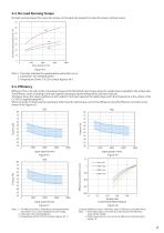
9-4. No Load Running Torque No load running torque: This means the torque on the input side required to rotate the reducer without a load. No load running torque (Ncm) Input speed (r/min) Figure 9-4 Note : 1. The value indicates the representative value after run-in. 2. Lubrication: Our standard grease 3. Temperature of the E CYCLO's surface: Approx, 40 °C 9-5. Efficiency Efficiency: This is the ratio of the actual input torque to the theoretical input torque when the rated torque is applied to the output side. The efficiency varies according to the input speed, load torque, grease temperature,...
Open the catalog to page 11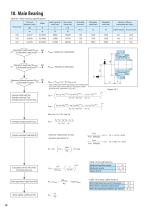
10. Main Bearing Table10-1 Main bearing specifications Pitch circle diameter of roller Basic dynamic rated load Basic static rated load Maximum radial load (Frmax) ≦ Allowable radial load Allowable radial load Allowable axial load Frmax = Maximum radial load Fr Maximum external moment (Mmax) NO ≦ Allowable moment Famax = Maximum axial load La Maximum axial load (Famax) ≦ Allowable axial load Mmax = Frmax (Lr + R )+Famax La ・ ・ * If the radial load and the axial load act in combination with each other, ensure that the total load is within the load value indicated in Fig. 10-2. Average radial load...
Open the catalog to page 12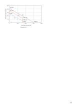
Allowable radial load (N) Allowable axial load (N)
Open the catalog to page 13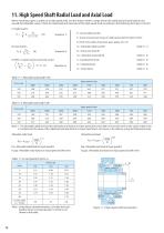
11. High Speed Shaft Radial Load and Axial Load When mounting a gear or pulley on a high speed shaft, use the reducer within a range where the radial load and axial load do not exceed the allowable values. Check the radial load and axial load of the high speed shaft according to the following formulas ([1] to [3]). Pr : Actual radial load (N) Tl : Actual transmission torque on high speed shaft of reducer (N^m) R : Pitch circle radius of sprocket, gear, pulley, etc. (m) Cf Fsi [3] When a radial load and axial load coexist ■CfFsi ^ 1 (Equation 3) Pro : Allowable radial load (N) (Table 11-1) Pa...
Open the catalog to page 14All SUMITOMO (SHI) Cyclo Drive Germany GmbH catalogs and technical brochures
 Paramax 9000 series
281 Pages
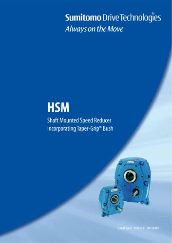 Helical Shaft Mount (HSM)
58 Pages
 Bevel Buddybox 4
60 Pages
 SERVO 6000
38 Pages
 BEVEL BUDDYBOX 4
248 Pages
 Cyclo® BBB5
270 Pages
 Fine Cyclo®
123 Pages
 PARAMAX ® 9000 Series
281 Pages
 Fine Cyclo UA Brochure
2 Pages
 Fine Cyclo Flyer
2 Pages
 Precision Drives Product Catalog
20 Pages
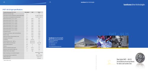 Fine Cyclo F4CF – UA 25
2 Pages
 Fine Cyclo F4CFS–UA 115
4 Pages
 Fine Cyclo F4C–C 25
4 Pages
 Paramax 9000
352 Pages
 Neo Hyponic
120 Pages
 Servo 100
58 Pages
 IB Series catalogues
94 Pages
 Servo 6000 series
6 Pages
 Cyclo® Drive 6000
139 Pages
 Paramax® 9000
352 Pages
 HSM series
58 Pages
 Astero series
186 Pages
 Servo Planetary Gears EPG
6 Pages
 Servo-Planetary Gears
4 Pages
 Centrifuge reducers
2 Pages
 Fine Cyclo®
114 Pages








Archived catalogs
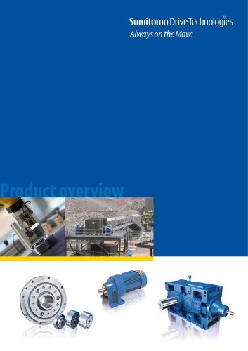 Product overview
16 Pages
- Actuator
- Electric gearmotor
- Planetary gearbox
- Electric actuator
- Coaxial gearhead
- Precision gearhead
- Right angle gearhead
- Direct current gear-motor
- Compact gearhead
- Solid-shaft gearhead
- Hollow-shaft gearhead
- Gear train gear reducer
- Gearbox for industrial applications
- Transmission gearhead
- Multi-stage gearhead
- Single-stage gearhead
- Industrial electric gearmotor
- Right angle electric gearmotor
- AC gear-motor
- Coaxial gearmotor