
- Catalogs
- SUMITOMO (SHI) Cyclo Drive Germany GmbH
- Motion Control Drives FINE CYCLO® F4C-D series

Motion Control Drives FINE CYCLO® F4C-D series

Motion Control Drives FINE CYCLO® F4C-D series
Catalog excerpts

Motion Control Drives FINE CYCLO® F4C-D series
Open the catalog to page 1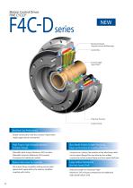
Motion Control Drives FINE CYCLO® Bearing of Output (Angular Contact Ball Bearings) Cycloid Disc Eccentric HighSpeed Shaft Ring Gear Housing Output Flange Excellent Cost Performance Simple construction with less number of parts than single stage reducer mechanism High Torque, High Allowable Moment Compact Design New Model Enables Simpler Designing Improved Interface for Coupling Machines Allowable peak torque: Maximum 24% increase Allowable moment: Maximum 45% increase (Compared to traditional models) Customer can choose the location of the attachment bolt on the output flange.This was done by...
Open the catalog to page 3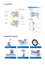
Main Example of Use Bearing of Output (Angular Control Ball Bearings) FINE CYCLO (F4C-D) Ring Gear Housing Oil Seal Eccentric HighSpeed Shaft Output Flange Carrier Slow Speed Shaft Roller High Speed Shaft Bearing Servo Motor Cycloid Disc Bearing for Eccentric Ring Gear Housing Pin Adaptor Plate Industrial Robot Axis Driving, Robot Slider Machine Tool Automatic Pallet Changer Drive Machine Tool Magazine Drive Machine Tool Automatic Pallet Pool Drive Liquid Crystal Transfer Robot Axis Driving, Robot Slider
Open the catalog to page 4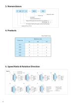
5. Speed Ratio & Rotation Direction Input : High Speed Output: Slow Speed Fixed : Ring Gear Input : High Speed Output: Ring Gear Fixed : Slow Speed Input : Slow Speed Output: Ring Gear Fixed : High Speed Input : Slow Speed Output: High Speed Input : Ring Gear Output: High Speed Fixed : Slow Speed Input : Ring Gear Output: Slow Speed Fixed : High Speed time, speed ratio is • i: Speed ratio = (Output Speed/Input Speed) ("-" indicates opposite
Open the catalog to page 5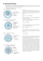
6. Operating Principles The reducer portion of the FINE CYCLO® is fundamentaly different in principle and mechanism from the involute gearing mechanism of competitive gearmotors. The unique speed reducer portion is an ingenious combination of the following two mechanisms: A combination of a planet gear and a fixed internal sun gear. In the FINE CYCLO®, the planet gear has cycloidal-shaped teeth and the sun gear has circular pin teeth. The number of teeth in the planet gear is one or two less than the sun gear. A constant speed internal gearing mechanism. Principle of internal Planetary Gearing...
Open the catalog to page 6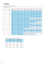
7. Rating Table D-1 Rating Table (Output rotation base) Output speed n2 (r/min) Frame size Reduction ratio Maximum acceleration T2A or deceleration torque T2B Peak torque for emergency stop T2max Rated output Input Allowable Rated output Input Allowable Rated output Input Allowable Rated output Input Allowable Rated output Input Allowable torque torque torque torque torque (Upper/N m) speed input power (Upper/N m) speed input power (Upper/N m) speed input power (Upper/N m) speed input power (Upper/N m) speed input power (Lower/kgf m) (r/min) (kW) (Lower/kgf m) (r/min) (kW) (Lower/kgf m) (r/min)...
Open the catalog to page 7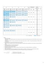
maximum Rated output Input Allowable Rated output Input Allowable Rated output Input Allowable Rated output Input Allowable input speed torque torque torque torque (Upper/N m) speed input power (Upper/N m) speed input power (Upper/N m) speed input power (Upper/N m) speed input power (r/min) (Lower/kgf m) (r/min) (kW) (Lower/kgf m) (r/min) (kW) (Lower/kgf m) (r/min) (kW) (Lower/kgf m) (r/min) (kW) Allowable maximum output speed(r/min) Equivalent On input shaft Upper/Moment of inertia (×10 -4kg m 2) Lower/GD2 (×10-4kgf m2) Notes: 1. Rated output torque Rated output torque implies allowable mean...
Open the catalog to page 8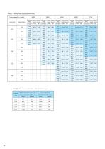
Table D-3 Rating Table (Input rotation base) Input speed n1 (r/min) Frame size Reduction ratio Table D-2 Maximum acceleration or deceleration torque Frame size Maximum acceleration T2A or deceleration torque T2B Peak torque for emergency stop T2max Rated output Output Allowable Rated output Output Allowable Rated output Output Allowable Rated output Output Allowable Rated output Output Allowable torque torque torque torque torque (Upper/N m) speed input power (Upper/N m) speed input power (Upper/N m) speed input power (Upper/N m) speed input power (Upper/N m) speed input power (Lower/kgf m) (r/min)...
Open the catalog to page 9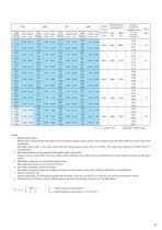
maximum Rated output Output Allowable Rated output Output Allowable Rated output Output Allowable Rated output Output Allowable input speed torque torque torque torque (Upper/N m) speed input power (Upper/N m) speed input power (Upper/N m) speed input power (Upper/N m) speed input power (r/min) (Lower/kgf m) (r/min) (kW) (Lower/kgf m) (r/min) (kW) (Lower/kgf m) (r/min) (kW) (Lower/kgf m) (r/min) (kW) Allowable maximum input speed(r/min) Equivalent On input shaft Upper/Moment of inertia (×10 -4kg m 2) Lower/GD2 (×10-4kgf m2) Notes: 1. Rated output torque Rated output torque implies allowable mean...
Open the catalog to page 10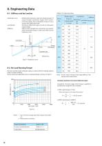
8-1. Stiffness and lost motion •Hysteresis curve Table D-4 Engineering data •Lost Motion Relationship between load and displacement of output flange (rotational angle) when load is removed slowly from allowable torque to zero torque, with fixed input shaft. Torsional deflected angle at ±3% of allowable output torque. Slope of the straight line connecting two points, when allowable torque is 50% and 100% on the hysteresis curve. 8-2. No Load Running Torque No load running torque indicates torque on input shaft for rotating reducer under no-load condition. Shown values are applicable only on standard...
Open the catalog to page 11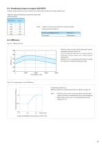
8-3. Breakaway torque on output shaft (BTO) Indicates torque necessary to start rotation from output side of reducer from stop without load. Table D-5 Value of breakaway torque from output side (starting torque) Frame size Notes: 1. Table D-5 shows max. torque from output side BTO. 2. Measurement Conditions Accuracy in assembled dimensions Standard grease 8-4. Efficiency Fig. D-9 Efficiency Curve Efficiency varies by input speed, load torque, grease temperature, reduction ratio, etc. Fig. D-9 indicates efficiency vs. input speed at allowable output torque with stable grease temperature. Efficiency...
Open the catalog to page 12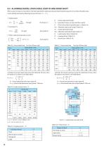
8-5. ALLOWABLE RADIAL LOAD & AXIAL LOAD OF HIGH SPEED SHAFT When a gear or sheave is mounted on the high speed shaft, radial load and axial load should be equal to or less than allowable value. Check radial & axial load by following the next formula ( When radial and axial load co-exist Pr·Lf Pa + Pro Pao Table D-6 Actual radial load : Actual radial load [N, kgf ] : Equivalent torque on input shaf [N m, kgf m] : Pitch circle radius of sprocket, gear, or sheave [m] : Allowable radial load [N, kgf ] (Table D-6) : Actual axial load [N, kgf ] : Allowable axial load [N, kgf ] (Table D-7) : Load location...
Open the catalog to page 13All SUMITOMO (SHI) Cyclo Drive Germany GmbH catalogs and technical brochures
 Paramax 9000 series
281 Pages
 Helical Shaft Mount (HSM)
58 Pages
 Bevel Buddybox 4
60 Pages
 SERVO 6000
38 Pages
 Motion Control DrivesE CYCLO
28 Pages
 BEVEL BUDDYBOX 4
248 Pages
 Cyclo® BBB5
270 Pages
 Fine Cyclo®
123 Pages
 PARAMAX ® 9000 Series
281 Pages
 Fine Cyclo UA Brochure
2 Pages
 Fine Cyclo Flyer
2 Pages
 Precision Drives Product Catalog
20 Pages
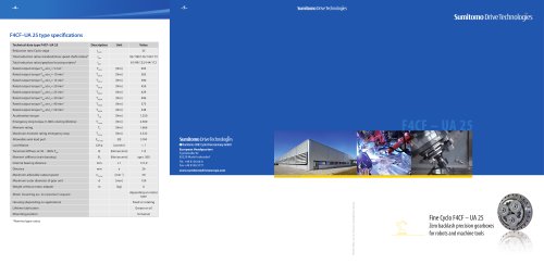 Fine Cyclo F4CF – UA 25
2 Pages
 Fine Cyclo F4CFS–UA 115
4 Pages
 Fine Cyclo F4C–C 25
4 Pages
 Paramax 9000
352 Pages
 Neo Hyponic
120 Pages
 Servo 100
58 Pages
 IB Series catalogues
94 Pages
 Servo 6000 series
6 Pages
 Cyclo® Drive 6000
139 Pages
 Paramax® 9000
352 Pages
 HSM series
58 Pages
 Astero series
186 Pages
 Servo Planetary Gears EPG
6 Pages
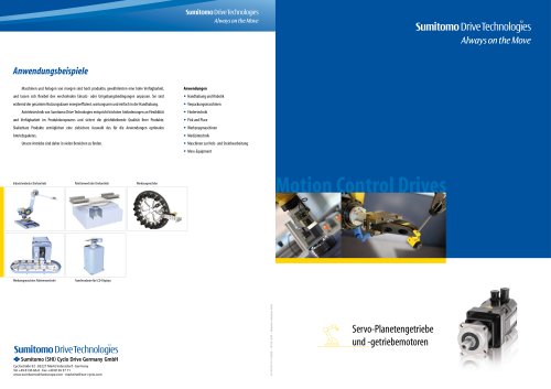 Servo-Planetary Gears
4 Pages
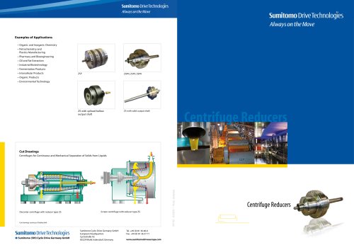 Centrifuge reducers
2 Pages
 Fine Cyclo®
114 Pages








Archived catalogs
 Product overview
16 Pages
- Actuator
- Electric gearmotor
- Planetary gearbox
- Electric actuator
- Coaxial gearhead
- Precision gearhead
- Right angle gearhead
- Direct current gear-motor
- Compact gearhead
- Solid-shaft gearhead
- Hollow-shaft gearhead
- Gear train gear reducer
- Gearbox for industrial applications
- Transmission gearhead
- Multi-stage gearhead
- Single-stage gearhead
- Industrial electric gearmotor
- Right angle electric gearmotor
- AC gear-motor
- Coaxial gearmotor