
- Catalogs
- SUMITOMO (SHI) Cyclo Drive Germany GmbH
- Motion Control Drives FINE CYCLO® F2C-C series

Motion Control Drives FINE CYCLO® F2C-C series

Motion Control Drives FINE CYCLO® F2C-C series
The FINE CYCLO® F2C-C series features a distinctive construction utilizing a planet gear with cycloidal-shaped teeth and a fixed internal sun gear with circular pin teeth, enabling a high velocity ratio.
The document highlights various industrial applications demonstrating the versatility of the FINE CYCLO® series.
This section explains the coding system for the F2C-C series, detailing reduction ratio, frame size, and configuration specifications.
Available models within the F2C-C series are listed, emphasizing different frame sizes and reduction ratios.
Details on calculating speed ratio and rotation direction using mathematical formulas are provided.
The document describes the unique planetary gearing and constant speed internal gearing mechanisms ensuring smooth motion transmission.
Tables provide ratings for input speed, reduction ratio, output torque, and allowable input power, essential for model selection.
Includes data on stiffness, lost motion, no-load running torque, and efficiency, with formulas for torsional deflection and efficiency compensation.
Information on main bearings, including loading points and moment stiffness, with formulas for external moments and allowable loads.
Guidelines for selecting the appropriate model based on torque, speed, and load conditions are outlined.
Design considerations and recommendations for optimal performance and longevity are provided.
Detailed drawings of F2C-C series models with dimensions and mounting details are included.
Formulas for calculating equivalent moment and axial load using coupling and shock factors are provided, with tables listing these values.
Includes tables detailing loading points, moment stiffness, allowable moments, and bolt specifications.
A flowchart outlines the selection process for frame size based on load characteristics, with an example calculation for a robot wrist application.
Guidelines for assembly, precision in dimensions, recommended tightening torques, and lubrication are provided, with overhaul recommendations.
Contact information for Sumitomo's subsidiaries and sales offices in Europe, Japan, and the USA is listed.
Catalog excerpts

Sumitomo DriveTechnologTes Motion Control Drives FINE CYCLO®
Open the catalog to page 1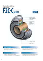
Motion Control Drives FINE CYCLO® Ring gear housing Output flange Grease is sealed inside the reducer. Simple construction with less number of parts Customers are released from the sealing work. than single stage reducer mechanism.
Open the catalog to page 3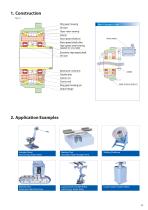
Ring gear housing Slow speed shaft pin Slow speed shaft roller High speed shaft bearing Eccentric high speed shaft Ring gear housing pin Output flange Servo motor Industral Robot I Machine Tool I Welding Positioner Axis Driving, Robot Slider I Automatic Pallet Changer Drive Machine Tool I Liquid Crystal Transfer Robot I Liquid Crystal Transfer Robot Automatic Pallet Pool Drive I Axis Driving, Robot Slider
Open the catalog to page 4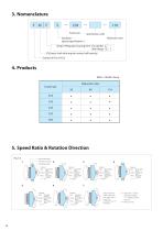
Specification suffix Reduction ratio Standard: − Special specification: S Shape of Ring gear housing Farm of a cylinder With flange 2C(Output shaft with angular contact ball bearing) Symbol of Fine CYCLO 4. Products Mark : Model Lineup Reduction ratio Frame size 59 5. Speed Ratio & Rotation Direction Fig. C-2 Slow Speed Shaft Ring Gear Housing High Speed Shaft Reducer Input : High Speed Shaft Output : Slow Speed Shaft Fixed : Ring Gear Housing i = -1/n 6 Increaser Input : Ring Gear Housing Output : High Speed Shaft Fixed : Slow Speed Shaft i = n+1 Reducer Input : High Speed Shaft Output : Ring...
Open the catalog to page 5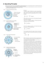
6. Operating Principles The reducer portion of the FINE CYCLO® is fundamentaly different in principle and mechanism from the involute gearing mechanism of competitive gearmotors. The unique speed reducer portion is an ingenious combination of the following two mechanisms: A combination of a planet gear and a fixed internal sun gear. In the FINE CYCLO®, the planet gear has cycloidal-shaped teeth and the sun gear has circular pin teeth. The number of teeth in the planet gear is one or two less than the sun gear. A constant speed internal gearing mechanism. Principle of internal Planetary Gearing...
Open the catalog to page 6
7. Rating Table C-1 Rating Table (Input rotation base) Input speed n1(r/min) Model Frame size Table C-2 Maximum acceleration or deceleration torque Frame size C25 C35 C45 C55 C65 Maximum acceleration or deceleration torque (N m) 1030 1962 3188 4316 6278 Rated output Output Allowable Rated output Output Allowable Rated output Output Allowable Rated output Output Allowable torque torque torque torque speed input power speed input power speed input power speed input power (Upper/N m) (Upper/N m) (Upper/N m) (Upper/N m) (Lower/kgf m) (r/min) (kW) (Lower/kgf m) (r/min) (kW) (Lower/kgf m) (r/min) (kW)...
Open the catalog to page 7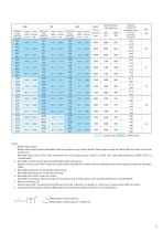
1000 Rated output torque (Upper/N m) (Lower/kgf m) Output Allowable Rated output torque speed input power (Upper/N m) (r/min) (kW) (Lower/kgf m) Output Allowable Rated output torque speed input power (Upper/N m) (r/min) (kW) (Lower/kgf m) maximum Output Allowable input speed speed input power (r/min) (r/min) (kW) Allowable maximum input speed(r/min) Equivalent On input shaft Upper/Moment of inertia (x10 -4kg m 2) Lower/GD2 (x10-4kgf m2) Notes: 1. Rated output torque Rated output torque implies allowable mean load torque at each output speed. Rated output torque for below 600r/min input is the...
Open the catalog to page 8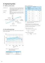
8-1. Stiffness and lost motion •Hysteresis curve Table C-3 Engineering data •Lost Motion Relationship between load and displacement of output flange (rotational angle) when load is removed slowly from allowable torque to zero torque, with fixed input shaft. Torsional deflected angle at ±3% allowable output Slope of the straight line connecting two points, when allowable torque is 50% and 100% on the hysteresis curve. Hysteresis loss 8-2. No Load Running Torque No load running torque indicates torque on input shaft for rotating reducer under no-load condition. Input speed r/min
Open the catalog to page 9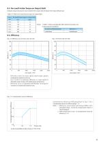
8-3. No-Load Friction Torque on Output Shaft Indicates torque necessary to start rotation from output side of reducer from stop without load. Table C-4 Value of no-load friction torque on output shaft Frame No-load friction torque on output shaft size Nm kgf m Accuracy in assembled dimensions Standard grease Notes: 1. Table C-4 shows average data after reducers have been run. 2. Measurement Conditions 8-4. Efficiency Fig. C-10 (Frame size C55-C65) Fig. C-9 Efficiency Curve (Frame size C25-C45) Input speed r/min Input speed r/min Efficiency varies by input speed, load torque, grease temperature,...
Open the catalog to page 10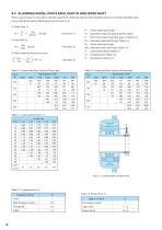
8-5. ALLOWABLE RADIAL LOAD & AXIAL LOAD OF HIGH SPEED SHAFT When a gear or sheave is mounted on the high speed shaft, radial load and axial load should be equal to or less than allowable value. Check radial & axial load by following the next formula (1)-(3). (1) Radial load Pr (3) When radial and axial load co-exist Pr Lf Pro Table C-5 Actual radial load Pro(Up: N/Down: kgf ) Frame size : Actual radial load [N, kgf ] : Equivalent torque on input shaft [N m, kgf m] : Pitch circle radius of sprocket, gear, or sheave [m] : Allowable radial load [N, kgf ] (Table C-5) : Actual axial load [N, kgf ]...
Open the catalog to page 11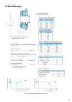
9. Main Bearings Pr: Actual radial load(N, kgf ) Pa: Actual axial load(N, kgf ) Table C-10 Span of Loading Points(mm) Frame size C25 C35 C45 C55 C65 Span of Loading Points Fig. C-13 Span between each loading point Note) Consult us if: Lr > 4 x L1 Table C-13 Coupling Factor Cf Load connection factor General purpose chain Machine gear or pinion Timing belt Table C-14 Shock factor FS1 Load Classification Uniform load (no shock) Moderate shocks Equivalent axial load Pae(N) Equivalent axial load Pae(N) Heavy shocks Fig. C-14 Diagram of Allowable Moment & Axial Load
Open the catalog to page 12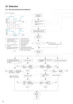
10. Selection 10-1. Flow Cart and Formula of Selection FIG. C-15 Load cycle Evaluate load characteristic Calculate of average input speed nE Calculate of average output torque TE Calculate of allowable rating output torque at average input speed TOE Selection Table (Table C-1) nA : Average input speed during tA : Acceleration time acceleration under tR : Normal running time condition defined in Fig. tB : Deceleration time nR C-15 tO tP nR : Input speed with normal T running nB : Average input speed during TA TR deceleration in Fig. C-15 TB nR nA = : Total running time : Standstill time : Time/Cycle...
Open the catalog to page 13All SUMITOMO (SHI) Cyclo Drive Germany GmbH catalogs and technical brochures
 Paramax 9000 series
281 Pages
 Helical Shaft Mount (HSM)
58 Pages
 Bevel Buddybox 4
60 Pages
 SERVO 6000
38 Pages
 Motion Control DrivesE CYCLO
28 Pages
 BEVEL BUDDYBOX 4
248 Pages
 Cyclo® BBB5
270 Pages
 Fine Cyclo®
123 Pages
 PARAMAX ® 9000 Series
281 Pages
 Fine Cyclo UA Brochure
2 Pages
 Fine Cyclo Flyer
2 Pages
 Precision Drives Product Catalog
20 Pages
 Fine Cyclo F4CF – UA 25
2 Pages
 Fine Cyclo F4CFS–UA 115
4 Pages
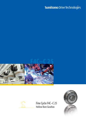 Fine Cyclo F4C–C 25
4 Pages
 Paramax 9000
352 Pages
 Neo Hyponic
120 Pages
 Servo 100
58 Pages
 IB Series catalogues
94 Pages
 Servo 6000 series
6 Pages
 Cyclo® Drive 6000
139 Pages
 Paramax® 9000
352 Pages
 HSM series
58 Pages
 Astero series
186 Pages
 Servo Planetary Gears EPG
6 Pages
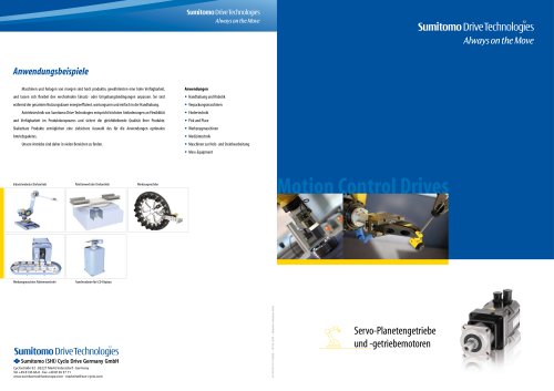 Servo-Planetary Gears
4 Pages
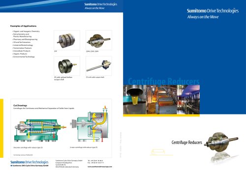 Centrifuge reducers
2 Pages
 Fine Cyclo®
114 Pages




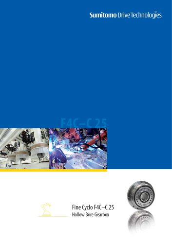




Archived catalogs
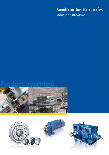 Product overview
16 Pages
- Actuator
- Electric gearmotor
- Planetary gearbox
- Electric actuator
- Coaxial gearhead
- Precision gearhead
- Right angle gearhead
- Direct current gear-motor
- Compact gearhead
- Solid-shaft gearhead
- Hollow-shaft gearhead
- Gear train gear reducer
- Gearbox for industrial applications
- Transmission gearhead
- Multi-stage gearhead
- Single-stage gearhead
- Industrial electric gearmotor
- Right angle electric gearmotor
- AC gear-motor
- Coaxial gearmotor